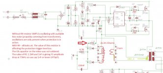
It is quite normal to have a spike on the leading edge of a current waveform and to filter it out with an RC. modern CMC PWM ICs often have leading edge blanking to avoid premature turn off. The RC will cause a phase shift in the current waveform if it's too big, although it's not as important in OCP as in CMC. Not sure if u have any filtering on it yet; I typically would start off trying 1k resistor, 100-470p capacitor.
You are using an out of date browser. It may not display this or other websites correctly.
You should upgrade or use an alternative browser.
You should upgrade or use an alternative browser.
IR2153 smps with short circuit protection.
- Thread starter norazmi
- Start date
Thanks MicrosiM
I have removed the snoober.
The idlle current dropped to 30mA, the mosfets are ice cold now. The waves have changed now and are more symetric. The current spikes at the current sense trafo are lower too.
So I am going in right direction anyway.
Now I have to sort out the over load protection. It is not working correct now, I have to find my fault somwhere, on the current sense trafo the high spikec are causing the SMPS to oscillate at the high load. I have soldered the BC550 transistor instead MCR100 and SMPS has turned off ok. I have to chec it again and maybe add some RC to smooth it a bit.
Good news,
1- Witch Mosfets you are using?
2- Temperature of Mosfets heat sink after running the SMPS for 30 minutes in idle?
3- How many watts from this smps has been extracted? 500W ? Voltage drop at full load?
4- Did you measure the voltage across the IR2153D while the SMPS is loaded?
5- Running frequency of your SMPS?
Can you post Scope waves of G+S of each Mosfet? (one measured at a time), SMPS loaded and not Loaded.
Only thing I don't like in the protection system used here, is that you have to restart the SMPS in order to reset the thyristor. So it would be better an AUTO RESET thing.
Regards
Thanks MicrosiM for response !!
1- irf840 from old atx
2- temperature of mosfet' heatsing i have measuret after 5 min of iddle and it wasn't rising anymore.
3- I do not have sufficient load, but 190W load on the one of the bus (one 45V secondary winding) - voltage drop was 1,2V with 680 uF capacitor. My plan is 400W total power
4- yes i have measured the voltage supply to IR2153 and is dropping a bit (12,8V)
5- 71kHz.
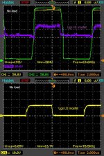
I have some Vgs measurements but with the snoobber. I have to measure whole think again with no snoober again.
1- irf840 from old atx
2- temperature of mosfet' heatsing i have measuret after 5 min of iddle and it wasn't rising anymore.
3- I do not have sufficient load, but 190W load on the one of the bus (one 45V secondary winding) - voltage drop was 1,2V with 680 uF capacitor. My plan is 400W total power
4- yes i have measured the voltage supply to IR2153 and is dropping a bit (12,8V)
5- 71kHz.
I have some Vgs measurements but with the snoobber. I have to measure whole think again with no snoober again.
Attachments
-
 Ugs HImosfet.jpg208.4 KB · Views: 59
Thanks MicrosiM for response !!
1- irf840 from old atx
2- temperature of mosfet' heatsing i have measuret after 5 min of iddle and it wasn't rising anymore.
3- I do not have sufficient load, but 190W load on the one of the bus (one 45V secondary winding) - voltage drop was 1,2V with 680 uF capacitor. My plan is 400W total power
4- yes i have measured the voltage supply to IR2153 and is dropping a bit (12,8V)
5- 71kHz.
I have some Vgs measurements but with the snoobber. I have to measure whole think again with no snoober again.
Looks nice, I was playing with IR2153D, I built small setup.
See wave across Mosfet S+D, I have zero heat in Mosfets also, SMPS running at the AUX supply, no feed yet from AUX winding of transformer.
I will implement a protection circuit soon also.
Will post updates.
Image 0163 is S+D
Image 0164 is G+S
Attachments
Last edited:
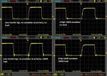
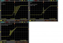
I have made some more tests. Bellow Vgs of lower mosfet with snoobber and without, load used 100W.
Are those spikes at the gate drive dangerous ??
And another difference, take a look at the amplitude of the Vgs. The ir2153 is supplied from V clamp resitor around 23k --> around 13.5mA of supply availible.
With NO snoobber the Vclamp diode in the IR2153 is holding the supply at around 15V (Vgs has max amplitude, current consumption lower than 13.5mA)) but with snoobber the current consumption by IR2153 is higher than 13,5mA and supply voltage is going down a bit (around 12,5V).
I will try snoobber with 100pF and see.
Attachments
-
 no snobber lo mosfet.jpg437.9 KB · Views: 58
Last edited:
I have made some more tests. Bellow Vgs of lower mosfet with snoobber and without, load used 100W.
Are those spikes at the gate drive dangerous ??
And another difference, take a look at the amplitude of the Vgs. The ir2153 is supplied from V clamp resitor around 23k --> around 13.5mA of supply availible.
With NO snoobber the Vclamp diode in the IR2153 is holding the supply at around 15V (Vgs has max amplitude, current consumption lower than 13.5mA)) but with snoobber the current consumption by IR2153 is higher than 13,5mA and supply voltage is going down a bit (around 12,5V).
I will try snoobber with 100pF and see.
Waves still looks good, You will get some spikes in all cases at Vgs of Mosfets.
Snubbers is my last worries here, Over current protection is the most important thing.
Today I draw ~ 350W 115VDC @ 3.2A from the SMPS, Mosfets heat after 3 minutes SMPS loaded is 34C. SMPS in Idle Zero heat.
I am still thinking of proper protection system but I think I will replace the Mosfets with 55A IGBTs. becasue a 20A Mosfet will not handle the short circuits and the over current things, I hope it will !!
Did you manage to implement any protection circuit?
Regards
MicrosiM
I am glad that you have time to answer my questions. I am total noob this is my first smps and I have to learn a lot.
If you would like give me some ideas and I can test them, the work can go bit quicker. What would you think about protection with resistor at lower mosfet ?
Yes I have managed to get over load protection working, with the short circuit at secondary winding (I am shorting it with set of the car bulbs for safety) the smps is turning off quickly and with no hiss.
With the schematic from post 1 --> the protection was not workin correct, the spikes were causing the smps to oscillate and make the hisss noise.
The key to the success was to put 2.2k resistor in between the gate of thyrystor, and it really maters. The current sense trafo is: 1 turn primary and 2x25 turns secondary, load resistor is 10R but i had to change it with 4,7R (and maybe I will have to reduce 2x25 turns to 2x15 turns and recalculate it) to get higher load capability. The main problem was hiss noise when protection was in action.
The good solution in my opinion would be to connect a small bipolar transistor and mosfet BS170 ''thyrystor wise'' instead MCR100.
I have putted 8R resistor across secondary winding in smps. The mosfet gate resistors I putted 33R
One question:
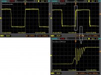
Does the oscillation present on secondary winding (5,17A load) has to be sorted out --> inductor after diodes or somethin else ??
The filtering cap is 680uF only for now.
I am glad that you have time to answer my questions. I am total noob this is my first smps and I have to learn a lot.
If you would like give me some ideas and I can test them, the work can go bit quicker. What would you think about protection with resistor at lower mosfet ?
Yes I have managed to get over load protection working, with the short circuit at secondary winding (I am shorting it with set of the car bulbs for safety) the smps is turning off quickly and with no hiss.
With the schematic from post 1 --> the protection was not workin correct, the spikes were causing the smps to oscillate and make the hisss noise.
The key to the success was to put 2.2k resistor in between the gate of thyrystor, and it really maters. The current sense trafo is: 1 turn primary and 2x25 turns secondary, load resistor is 10R but i had to change it with 4,7R (and maybe I will have to reduce 2x25 turns to 2x15 turns and recalculate it) to get higher load capability. The main problem was hiss noise when protection was in action.
The good solution in my opinion would be to connect a small bipolar transistor and mosfet BS170 ''thyrystor wise'' instead MCR100.
I have putted 8R resistor across secondary winding in smps. The mosfet gate resistors I putted 33R
One question:
Does the oscillation present on secondary winding (5,17A load) has to be sorted out --> inductor after diodes or somethin else ??
The filtering cap is 680uF only for now.
Attachments
-
 wtiddle.jpg307.8 KB · Views: 64
 -
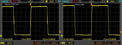 pierrw220w.jpg198.1 KB · Views: 57
 -
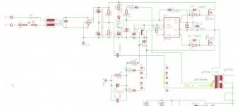 smps schematic.jpg20.6 KB · Views: 209
 -
 ir2153 no traffo 4.jpg210.2 KB · Views: 102
MicrosiM
I am glad that you have time to answer my questions. I am total noob this is my first smps and I have to learn a lot.
If you would like give me some ideas and I can test them, the work can go bit quicker. What would you think about protection with resistor at lower mosfet ?
Yes I have managed to get over load protection working, with the short circuit at secondary winding (I am shorting it with set of the car bulbs for safety) the smps is turning off quickly and with no hiss.
With the schematic from post 1 --> the protection was not workin correct, the spikes were causing the smps to oscillate and make the hisss noise.
The key to the success was to put 2.2k resistor in between the gate of thyrystor, and it really maters. The current sense trafo is: 1 turn primary and 2x25 turns secondary, load resistor is 10R but i had to change it with 4,7R (and maybe I will have to reduce 2x25 turns to 2x15 turns and recalculate it) to get higher load capability. The main problem was hiss noise when protection was in action.
The good solution in my opinion would be to connect a small bipolar transistor and mosfet BS170 ''thyrystor wise'' instead MCR100.
I have putted 8R resistor across secondary winding in smps. The mosfet gate resistors I putted 33R
One question:
Does the oscillation present on secondary winding (5,17A load) has to be sorted out --> inductor after diodes or somethin else ??
The filtering cap is 680uF only for now.
I am here to learn and to help as much as I can. I always answer when I have time.
I am glad that you have success with the over current circuit working. How do you reset the SMPS when it enters protection?
I don't like the idea of using resistor at lower mosfet, cos it will not work all the time, some times it will miss, and will cause the SMPS to blow. I tested that years ago.
The only way of testing short circuit is to SHORT the output of the SMPS, also you have to short the SMPS output and then power up, and if those tests passed, then GOOD!
In the last few days, I blown many mosfets testing, the thing that makes me interested into the IR2153 as SMPS controller, it works like magic, but making it as full SMPS is a complex task indeed, Mosfets running cool, Even when the SMPS is loaded 400W, they become just warm. witch is perfect! also its very cheap, very simple. a few parts and you run!
I dont understand the (Hiss sound) you mentioned, why you hear it when the SMPS enters protection? can you upload a small video?
Your waves looks very nice at the 5.17A, I dont think you need to worry about the waves for now, all can be sorted out with Snubbers, witch is last worries.
** Opps, I saw 20.4MHz on scope, I am sure that the oscillation is happening, can you post a picture of your SMPS?
Regards
Last edited:
Hard to say for sure without the thing in front of me, but the ringing on the secondary waveform is probably from the transformer's leakage inductance ringing with the capacitance of a reverese biased secondary rectifier. It's easily snubbed out with either an RC snubber across the secondary winding or separate snubbers across each diode. The separate snubbers may be the better solution especially if the rectifier diodes aren't Schottkys as a snubber directly across the secondary winding doesn't really work in the period when neither diode is conducting. Snubber is especially useful if you are using standard PN junction diodes because of their relatively high parasitic capacitance and reverse recovery time compared to Schottkys.
Standard process for RC snubber where the ringing is down to parasitics you don't know:
Add a capacitance (usually start at 100pF and tweak from there) in parallel with the ringing semiconductor until the ringing frequency halves, then you know the semiconductor's capacitance is 1/3 that of the added capacitor. Add a resistor in series with this capacitor equal to the parasitic capacitance's reactance at the resonant frequency (or inductances reactance since they're equal at resonant frequency) Formula Rsnb=1/(2*pi*Cdiode*Fringing). Try to keep lead lengths short to minimise inductance in the snubber which might complicate things.
KX36
Thanks for response !! I will try to match the snubbers at secondary winding. I do not have inductors after diodes.
The over load protection test:
https://www.youtube.com/watch?v=vedNDHRhi_8&feature=youtu.be
Sorry that I was so quiet but I got pants full of **** while doing this test
Next time I will speak a bit.
The SMPS survives short circuit at secondary winding and start up with short circuit.
The load is 8R resistor at 45V secondary winding, the fuse in SMPS is 1A slow and is not blowing even under load.
I like to work with IR2153 too, it is very simple.
RESET --> disconnect from mains for 15-20s and done.
Attachments
-
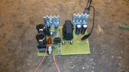 smps 1.jpg156.5 KB · Views: 205
Last edited:
KX36
Thanks for response !! I will try to match the snubbers at secondary winding. I do not have inductors after diodes.
The over load protection test:
https://www.youtube.com/watch?v=vedNDHRhi_8&feature=youtu.be
Sorry that I was so quiet but I got pants full of **** while doing this test
Next time I will speak a bit.
The SMPS survives short circuit at secondary winding and start up with short circuit.
The load is 8R resistor at 45V secondary winding, the fuse in SMPS is 1A slow and is not blowing even under load.
I like to work with IR2153 too, it is very simple.
RESET --> disconnect from mains for 15-20s and done.
Looks very nice, But I noticed that you made the short circuit test at the + & GND? because I still see the right LED ON. Try at the + & -, don't worry it should pass, because making the short circuit at the + & GND , or - & GND is more critical.
Please post the protection circuit section in PDF file if you can, I would like to give it a try. If you dont mind !!
Only problem is the reset thing, if I figure out the way to reset the thyristor every 2 seconds, it would be great!
Regards
I have tested +bus and -bus, worked ok and 1A fuse at the mains is ok.
Schematic bellow, the 1nF cap on the gate of mcr100 was not soldered on the video.
The resetting after 2s should be no problem but more transistors have to be used. Similar setup DC detection with delayed ON function is applied on the right side of the board, it is used to drive relay for the speakers protection, trigger level can be adjusted from 0.6V and delay can be adjusted too (just replacement of few caps).
Tomorrow is my last day before holidays (14 days off) so rest of the work must wait till then. I will try setup with the mosfet BS170.
I prefer manual reset because if something wrong will go with amplifier I prefer the smps to be switched off permanently.
Attachments
-
 schemat v3.3.jpg21.1 KB · Views: 414
Yes I am using IRF840 in prototype board. If they survived it means all good.
I will try again with jpg file.
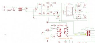
I have made small boo boo on the drawing, I have forgotten to connect center point of current sense transformer sec winding to GND_A, it is connected.
I will try again with jpg file.
I have made small boo boo on the drawing, I have forgotten to connect center point of current sense transformer sec winding to GND_A, it is connected.
Attachments
-
 smps schematic jpg.jpg173.3 KB · Views: 318
That looks much better. Well done.
You can oversize the capacitor a bit and calculate the snubber resistor based on what it should have been. It just needs to have insignificant reactance compared to the resistor at the ringing frequency. Too low and the snubber is less effective, too high and the dissipation in the snubber increases more than it has to.
In other words, 220pF should be fine as long as your snubber resistor is based on the 150pF you think it should have been (e.g. if 150pF halves the ringing freqency, the diode capacitance is 150/3pF = 50pF and the snubber resistor is 1/(2*pi*50pF*20.4MHz) = 156 ohms.
It should be possible to calculate the diode capacitance just from knowing the capacitance you added and the change in frequency, but I need to grab a bit of paper to do so. It's more complicated than the previous formula as that formula works by cancelling a lot out when the halving frequency condition is true. Still simple maths though. You can rarely get rid of the spike completely, so further calculation might not yield too much improvement.
Incidentally you can also calculate the leakage inductance at the secondary to be 1.2uH with this information.
Calculating the dissipation in the snubber resistor is more complicated, so watch how warm that gets.
Last edited:
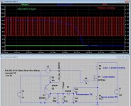
I did the maths based on the difference adding 100pF to the capacitance of the LC tank circuit makes according to your picture, dropping its ringing frequency from 20.4MHz to 17.8MHz and the results I got for the parasitics were L=191nH, C=319pF. Sorry my maths is an absolute mess so I can't show the working. If this is accurate, the snubber would be 1nF, 24R. Such a snubber might make for a nicer waveform but possibly at the expense of more dissipation in the resistor. Maybe try it and see.
Here's a sim I used to check my maths:

Have a nice holiday!
Regards,
Matt
Here's a sim I used to check my maths:
Have a nice holiday!
Regards,
Matt
Last edited:
I'm at work at the moment so don't have the file here, but this simulation is just a basic ideal LC filter with various RC networks in parallel with the capacitor. Probably not much use beyond what I posted. You could poke it with a square wave and see how it does but your circuit is not exactly the same as this. As yours has some intrinsic damping and an ideal LC. Filter doesn't.
What I don't get is if this is accurate it doesn't make sense that u said 220pF was too much and you thought it was around 150pF. What you say implied you tried 220pF and it lowered the frequency to below 10.2MHz whereas if this is true it would be around 15.7MHz
What I don't get is if this is accurate it doesn't make sense that u said 220pF was too much and you thought it was around 150pF. What you say implied you tried 220pF and it lowered the frequency to below 10.2MHz whereas if this is true it would be around 15.7MHz