You are using an out of date browser. It may not display this or other websites correctly.
You should upgrade or use an alternative browser.
You should upgrade or use an alternative browser.
Car SMPS Project
- Thread starter badboy_6120
- Start date
badboy_6120
Member
@badboy
If the alternator is capable of delivering 90 amps then it should be strong enough to give the full voltage at 70A with adequate revs from the engine. The voltage regulator in the alternator will do this job.
thanks man
badboy_6120
Member
Hi again
I manage to build a full bridge inverter to drive my amplifier in the car
everything is good except mosfet's overheating under load
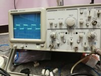
here's a picture of primary transformer without any output load :
*** Oscilloscope Volt/Div is on 2 (((Channel 2))) and the probe is set to X10
and here's a picture of primary transformer with 500W load:
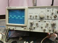
Could those sparks be the cause of mosfets overheating ?????
I manage to build a full bridge inverter to drive my amplifier in the car
everything is good except mosfet's overheating under load
here's a picture of primary transformer without any output load :
*** Oscilloscope Volt/Div is on 2 (((Channel 2))) and the probe is set to X10

and here's a picture of primary transformer with 500W load:

Could those sparks be the cause of mosfets overheating ?????
Last edited:
badboy_6120
Member
@badboy
Mosfet current rating should be 3 times the operating current. EX, for 3 amp load max current of mosfet is 9 amp.
voltage spike will not help either, did you try to suppress it?
I use two IRF1404 in parallel at each channel
at 500W in the output there should be around 40A in input going through the masfets!!!!
I used snubber as well to controll those sparks and I did eliminate them but the overheating is still there
Silvio
Well-known member
I use two IRF1404 in parallel at each channel
at 500W in the output there should be around 40A in input going through the masfets!!!!
I used snubber as well to controll those sparks and I did eliminate them but the overheating is still there
Did you buy genuine transistors? Be careful as it happened to me. I bought IRF740 from aliexpress and also E-bay and they where fakes. They could not withstand the current and at only 1/3 the current they where getting very hot.
I Broke one of them in the vice and saw that the die was half the size than a genuine one.
Note A mosfet is made from a lot of small mosfets in parallel diffused on the same die. If the die is small then there is not the amount there should be hence the current rating will suffer.
I have a video on Youtube where I found a way to check them by measuring the internal capacitance. (The more capacitance the more fets there are on the chip)
Lastly IRF1404 can withstand 115 amps at a case temperature of 100 degrees Celsius. They are suppose to handle the load very easily.
Here is the link https://www.youtube.com/watch?v=gRRfb5YxvIA
Regards Silvio
badboy_6120
Member
Did you buy genuine transistors? Be careful as it happened to me. I bought IRF740 from aliexpress and also E-bay and they where fakes. They could not withstand the current and at only 1/3 the current they where getting very hot.
I Broke one of them in the vice and saw that the die was half the size than a genuine one.
Note A mosfet is made from a lot of small mosfets in parallel diffused on the same die. If the die is small then there is not the amount there should be hence the current rating will suffer.
I have a video on Youtube where I found a way to check them by measuring the internal capacitance. (The more capacitance the more fets there are on the chip)
Lastly IRF1404 can withstand 115 amps at a case temperature of 100 degrees Celsius. They are suppose to handle the load very easily.
Here is the link https://www.youtube.com/watch?v=gRRfb5YxvIA
Regards Silvio
as you said I checked the output capacitance of my mosfets and I get about 8.7 nf
I think they are good to go
Silvio
Well-known member
as you said I checked the output capacitance of my mosfets and I get about 8.7 nf
I think they are good to go
You cannot tell exactly until you make some comparisons with a known genuine fet. The input capacitance tend to vary according to frequency and voltage of operation.
Do they get hot at a lower load say at 20A? Do not get fooled about the parameters as current is always limited in these fets especially if they are in TO220 package. The transistor leads themselves cannot carry more than 60 to 70 amps and they must be kept as short as possible. The traces at the pcb should be wide as possible to eliminate any heating.
If all seems good and wave form, frequency, flux density etc then it could be the fets themselves not capable for the load.
I would like you to check the voltage at the gates when operation on high load. See that it is not dropping in any way especially the high side gate. See also that you have adequate dead time.
Silvio
Last edited:
badboy_6120
Member
Thanks Dear Silvio for your helps
So it turned out that my multi meter was reading incorrectly (Broken) and the temp on the back metal part of mosfets never reach 50 degrees with a low value snubbers (I use another multi meter)
So now I need to know how exactly I can choose the best values for my snubbers????? (As I see experimentally higher the value of Capacitor in snubbers between Drain @ Source, Lower the amount of Sparks and therefore less heating on mosfets)
I manage to draw my Schematics and also took some pictures of my project:
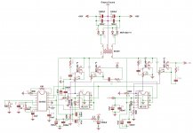
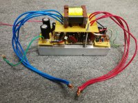
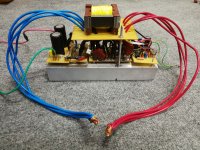
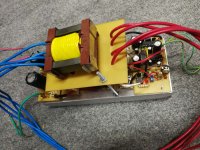
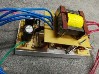
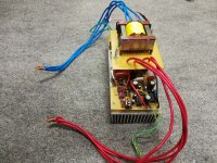
Could you also look at the schematic and see if there is any problem with it??????
Thank you
So it turned out that my multi meter was reading incorrectly (Broken) and the temp on the back metal part of mosfets never reach 50 degrees with a low value snubbers (I use another multi meter)
So now I need to know how exactly I can choose the best values for my snubbers????? (As I see experimentally higher the value of Capacitor in snubbers between Drain @ Source, Lower the amount of Sparks and therefore less heating on mosfets)
I manage to draw my Schematics and also took some pictures of my project:


Could you also look at the schematic and see if there is any problem with it??????
Thank you
badboy_6120
Member
I also use one 2.7 ohms resistor for every two mosfets parallel in every channel
should I use a higher resistor value or use a seperate resistor for each one of the 2 parallel mosfets??
should I use a higher resistor value or use a seperate resistor for each one of the 2 parallel mosfets??
Silvio
Well-known member
Hi Badboy
The project looks quite fine but I think you can arrange a bit the layout of the PCB. I do not know if space is very important or not but I think fitting the trafo on the main pcb near the switching transistors will be better and have shorter leads. I think you can make the control circuit on a separate board and fitted with a pin header. You can also make more than one pin header. This will save you space and get also low profile.
I am glad you found the problem, 50 degrees is very normal operating temperature.
Regarding gate resistors I think using a separate resistor for each fet will be a better choice thus the gate charge will be more equal to each fet. Doing it this way you will need to use a 6 ohm resistor with each fet thus having them in parallel will bring the total resistance of 3 ohms which is seen by the IR2110
Some considerations for gate resistor and snubbers. I have a blog post here and shows step by step how to work out the gate resistor value according to the fets used and current handling of the fet driver (IR2110 in your case) This chip can deliver a maximum of 2amps of drive current so this must not be exceeded. Do not forget to double your values as now you have 2 parallel fets . You will also find how to calculate and adopt a simple resistive and capacitive snubber for the smps in the same blog post. Download the pdf in the post its all explained there.
Link http://www.diysmps.com/forums/entry...-snubber-components-and-driver-gate-resistors
regards Silvio
Last edited:
badboy_6120
Member
thank you for your tips
I used 2 seperate 6 ohms resistors for 2 parallel mosfets and this lower down the amount of sparks
I still need to use some snubbers
I will calculate the values using your PDF as soon as I can
Thanks again
I used 2 seperate 6 ohms resistors for 2 parallel mosfets and this lower down the amount of sparks
I still need to use some snubbers
I will calculate the values using your PDF as soon as I can
Thanks again
badboy_6120
Member
badboy_6120
Member
should I take 150 or 35 as T on??
badboy_6120
Member
thanks a lot
if it's possible could you tell me how did you get 10 ohms from the formula?
I mean what values did you use from the datasheet
if it's possible could you tell me how did you get 10 ohms from the formula?
I mean what values did you use from the datasheet
Silvio
Well-known member
Hi badboy
The prorogation delay is the time for the IR2110 to react when given a pulse from the SG3525. we don't take that into consideration.
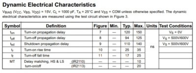
You will use the turn on rise and fall time instead using the typical value. In this case 25nS and 17nS
We also use the total gate charge of the fet used in this case take the average of 180nC (160nC-200nC)
I re-worked the math for you as I found a small mistake and re calculated all. I adjusted also for 2 parallel fets having around 0.9amps of current each so this brings a total of around 1.8 amps on the IR2110 at 13.5v. This voltage of 13.5v is more realistic considering some voltage drop in the wiring and connections etc. However at 14.7v this brings a maximum of 1.96amps to the IR2110.
The total switching time of t-on plus t-off plus fall time of IR2110 came to 440nS or 0.44mS which is very good. With a dead time of 1uS you will have more than 50% time until the next switching cycle. This will also give ample time for the core to discharge all its magnetic flux.
The gate resistor to each fet is to be 15 ohms so IR2110 will see a combined resistance of 7.5 ohms ( 13.5v / 7.5 ohms = 1.8 amps)
I cannot show my working as its such a pain in the a.......rs to write it all down. With the figures I gave you you can plug them in the formulas and you will arrive with the same answers.
Regards Silvio
badboy_6120
Member
thanks man
I get it now
I appriciate your helps
I get it now
I appriciate your helps
badboy_6120
Member
So I replace the gate resistors with 15 ohms resistors for each fets and now the fets reaches to 50 degrees at 600W load
now there's a problem with current transformer for protection board and it's getting really hot under load
I used a yellow toroidal core from pc power supply
should I use different core for this much current passing through it?
now there's a problem with current transformer for protection board and it's getting really hot under load
I used a yellow toroidal core from pc power supply
should I use different core for this much current passing through it?
Silvio
Well-known member
So I replace the gate resistors with 15 ohms resistors for each fets and now the fets reaches to 50 degrees at 600W load
now there's a problem with current transformer for protection board and it's getting really hot under load
I used a yellow toroidal core from pc power supply
should I use different core for this much current passing through it?
If you want to check that the gate resistors are good just check the voltage at the gate to source with the scope. If the voltage is above 10 volts than the gate resistors are good at that value. 50 degrees on the fets is not so much you can add fan to cool things up. You may be pulling around 60 amps from the battery at 600w at 80% efficiency. Are you pulling a continuous load? or with amplifier?
Regarding current trafo it may be the case that you have too much turns on the secondary of the current trafo. Make less turns and put a load resistor according to the tripping voltage wanted in your smps. It is not the current passing but the load on it with the secondary turns and load resistor.

