You are using an out of date browser. It may not display this or other websites correctly.
You should upgrade or use an alternative browser.
You should upgrade or use an alternative browser.
Audio smps 700w (IR2153)
- Thread starter Silvio
- Start date
hello silvio and stewin, i will go with ir2153, easy, cheap, and has and option there is many way to limit the current a.k.a OCP with ir2153.
hello there norazmi , long time man welcome back. i am trying to in-cooperate pfc with my smps , because i dont use regulated smps , at times when mains voltage is at 210vac the output voltage is low . when at 220vac mains all is well. but at 250vac the output is high.
the reason i was making pfc ,it is so that the output voltage will remain same from 90vlts ac up to 350vac
@ silvio what core may i use and how many turns should i turn? i have lots of iron powder cores t130-10(black core) t130-26(white yellow core) and t130-52(blue green core)
which of the above should i use and how many turns should i turn?
thanking you in advance steve
Silvio
Well-known member
@ Steven
Quote
@ silvio what core may i use and how many turns should i turn? i have lots of iron powder cores t130-10(black core) t130-26(white yellow core) and t130-52(blue green core)
which of the above should i use and how many turns should i turn?
Regarding the core used this is based on firstly the power to deliver. This has to be large enough so that it can handle the power that it has to deliver without saturation. To my believe a sandust core is suitable for this purpose. Microsim can also recommend the type of core to be used in pfc as he had already experimented with it.
I Have an XL file using the NCP1653 PFC chip to work out the pfc circuit according to your need but I cannot upload it here as it is saying that the file is not valid. You can send me your mail address and I will post it to you.
regards Silvio
NCP1635 is not the best choise chip for PFC, but you could experiment with it.
Cores from https://www.mag-inc.com/ will do the job perfectly, look for the suitable core for your application.
You may also view here my latest PFC experiments.
[video=youtube;_sbvyMyv3Qs]https://www.youtube.com/watch?v=_sbvyMyv3Qs[/video]
Hope that helps
Cores from https://www.mag-inc.com/ will do the job perfectly, look for the suitable core for your application.
You may also view here my latest PFC experiments.
[video=youtube;_sbvyMyv3Qs]https://www.youtube.com/watch?v=_sbvyMyv3Qs[/video]
Hope that helps
NCP1635 is not the best choise chip for PFC, but you could experiment with it.
Cores from https://www.mag-inc.com/ will do the job perfectly, look for the suitable core for your application.
You may also view here my latest PFC experiments.
[video=youtube;_sbvyMyv3Qs]https://www.youtube.com/watch?v=_sbvyMyv3Qs[/video]
Hope that helps
like which colour and size of core sir?
@ Steven
Quote
@ silvio what core may i use and how many turns should i turn? i have lots of iron powder cores t130-10(black core) t130-26(white yellow core) and t130-52(blue green core)
which of the above should i use and how many turns should i turn?
Regarding the core used this is based on firstly the power to deliver. This has to be large enough so that it can handle the power that it has to deliver without saturation. To my believe a sandust core is suitable for this purpose. Microsim can also recommend the type of core to be used in pfc as he had already experimented with it.
I Have an XL file using the NCP1653 PFC chip to work out the pfc circuit according to your need but I cannot upload it here as it is saying that the file is not valid. You can send me your mail address and I will post it to you.
regards Silvio
hi silivio , in the video ,wayuk used a black core for input inductor, my email is stevekamala@gmail.com
hi all i have finished drawing my version of smps with pfc. based on the above pfc , it will be about 1,200 wts , i will use irfp 460 fets .
your views and comments are highly welcomed and appreciated.")
 View attachment gtG pfc half bridge gdt smps dip schematic.pdf
your views and comments are highly welcomed and appreciated.
View attachment gtG pfc half bridge gdt smps dip schematic.pdfSilvio
Well-known member
Hello Steven, I was just looking at the schematic and these are a few of my taughts.
1) Why is the PFC voltage set so low? Usually we start at around 360 to 380vdc. Do not forget that the mains voltage could rise to 250Vac. This will bring a voltage of 353vdc at the pfc dc line. This voltage must always be higher than the input mains voltage. I would rather start at 370v at least. It would be best to try the pfc stage alone first and see how it holds the voltage with load. Load to 6 amps will be adequate. You may need to trim the feedback and holding time. You may need to adjust the turns in the primary to take the new voltage.
2) Regarding the oscillator and GDT, Well have you tried this before to see how it works? Keep things simple because at times the more things you add to the gate circuit the more the waveform distorts. A good waveform to the gate is the key to a successful smps. A diode parallelled with a resistor is enough usually.
3) Regarding SG chip well I have seen a lot of circuits of pro amplifiers and the way they hook this chip when no regulation is needed then proceed this way. The non inverting input goes directly to V-ref. The inverting input goes directly to ground. The compensating pin 9 is left open. The discharge resistor at pin 7 is usually 100 to 120 ohms at the frequency of operation you are using CT 1nF and RT 10K (65Khz) This gives a dead time of around 500nS to 600nS.
Lastly I am still concerned about the voltage rating of the IRFP460 in the pfc stage. Voltage spikes may exceed the voltage rating.
Above everything else you need to try it out to find out.
Good luck Regards Silvio.
Last edited:
PFC should be set at 380VDC as minimum as going lower than that requires redesign of the loop.
And the most important thing to remember is to test at 100VAC as this is the point that shows if your PFC is working or not.
Also, the point when you go from no load to full load is very critical as it will confirm your entire design success.
Hope that helps
And the most important thing to remember is to test at 100VAC as this is the point that shows if your PFC is working or not.
Also, the point when you go from no load to full load is very critical as it will confirm your entire design success.
Hope that helps
thanks for the replies silvio and microsim . the smps i drew it from my existing smps which has worked well , i just added the pfc side and adjusted the gate drive to be like the above 2k smps with pfc .below the schematic of my previous smps which i have been using
View attachment gtG smps lp small bottom.bmpView attachment gtG smps lp small pcb artwork.pdfView attachment gtG smps lp small components full.pdf
 View attachment gtG smps lp small schematic.pdf
View attachment gtG smps lp small bottom.bmpView attachment gtG smps lp small pcb artwork.pdfView attachment gtG smps lp small components full.pdf
View attachment gtG smps lp small schematic.pdfAttachments
-
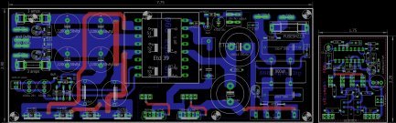 gtG smps lp small pcb full.jpg23.7 KB · Views: 76
 -
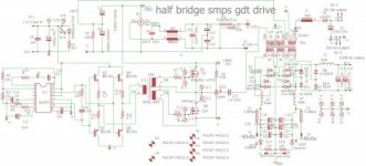 gtG smps lp small schematic.jpg20.9 KB · Views: 77
Last edited:
PFC should be set at 380VDC as minimum as going lower than that requires redesign of the loop.
And the most important thing to remember is to test at 100VAC as this is the point that shows if your PFC is working or not.
Also, the point when you go from no load to full load is very critical as it will confirm your entire design success.
Hope that helps
hello microsim . i have updated schematic as per the recomendation , is all o.k ?View attachment gtG lp smps fb ver 1 dip drive schematic.pdfView attachment gtG lp smps fb ver 1 dip drive schematic.gif
Silvio
Well-known member
Hi Ionut,I read this post a few times, I also watched a video on youtube but I still don't understand which part of the scheme you kept and how you added the current transformer in the scheme. maybe you can help me understand. thank you very much
At the time I shared this SMPS I experimented further with different pin headers thus making further options for the protection circuit. The one you see on youtube is with current transformer and scr and also a high frequency soft start. This came out the best version to my believe but its not auto reset as the current limiter. Each time the protection works the smps has to be switched off for 15 seconds to reset again to operation mode. I am posting the V2 PDF so you can choose the different options.
One last detail is for the preamp supply is better to use 15v regulators instead of 12v regulators.
Good luck regards Silvio
Attachments
IVANELECTRIC
Member
Hi Silvio, good afternoon. I built this smps, left it at 62kHz (it has primary RC snubber). I have 265W at the input and 165W at the output, a low efficiency. The nucleus has a central gap ?.
On the other hand, I would be interested to know how the frequency at which the source is going to be working is calculated? From already thank you very much!
Greetings from Argentina
On the other hand, I would be interested to know how the frequency at which the source is going to be working is calculated? From already thank you very much!
Greetings from Argentina
Silvio
Well-known member
If you built the 700w smps it is half bridge topology. The transformer must NOT have any gap in the center core. If you are measuring the input with volt meter and amp meter you will not get the true power because of the power factor. The input shall be measured with a watt meter to make your comparisons. On the secondary DC side you can measure with volt and amp meter and you get a good result.
Regarding the frequency of operation it can be between 60-65Khz.
If you want to know how to calculate the RC values for the frequency you can check the datasheet of the IR2153.
Regards Silvio
Regarding the frequency of operation it can be between 60-65Khz.
If you want to know how to calculate the RC values for the frequency you can check the datasheet of the IR2153.
Regards Silvio
IVANELECTRIC
Member
I used voltmeter and ammeter like you to measure input and output. I do not have a wattmeter. How do you know if 60kHz or 90kHz is better?If you built the 700w smps it is half bridge topology. The transformer must NOT have any gap in the center core. If you are measuring the input with volt meter and amp meter you will not get the true power because of the power factor. The input shall be measured with a watt meter to make your comparisons. On the secondary DC side you can measure with volt and amp meter and you get a good result.
Regarding the frequency of operation it can be between 60-65Khz.
If you want to know how to calculate the RC values for the frequency you can check the datasheet of the IR2153.
Regards Silvio
Silvio
Well-known member
Regarding the transformer I do not know what number of turns you used in the primary. If you have a gap in the transformer the inductance for a given number of turns will be lower. The number of turns are calculated according to the switching frequency. The less inductance you have the higher the switching frequency must be. This topology HB does not need a gap in the center core of the transformer. The number of turns shown in the schematic are for a transformer ETD39 without a gap. Your transformer has a gap and the inductance becomes rather low for the number of turns. I am posting a link for you for a Russian video so that you will see how to fill the gap in your transformer.
watch from 2:10 to 4:10. Link
If the filling of the center core becomes higher you can sand it down with a piece of sand paper placed on a flat surface (a piece of glass is better)
You will notice that only one half of the core has a short center leg the other half has its 3 legs equal. You will fill the half with the short center leg.
Using a higher frequency may give you problems with heating of the mosfets and also the transformer.
Regards Silvio
watch from 2:10 to 4:10. Link
You will notice that only one half of the core has a short center leg the other half has its 3 legs equal. You will fill the half with the short center leg.
Using a higher frequency may give you problems with heating of the mosfets and also the transformer.
Regards Silvio