Compact Aux power supply for smps

Silvio

Well-known member
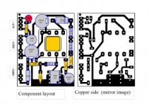
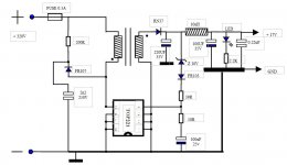
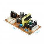
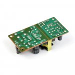
Here I am presenting an auxiliary power supply meant to be fitted with a SMPS of half or full bridge. The output voltage was chosen to be 17v which is quite ideal for this purpose. However this voltage can be varied to suit the particular need . The TOP221P chip is utilized as this comes in various shapes as 8 pin DIL or TO220. The chip comes also in various wattages such as 9 to 20 watts in DIL and SMD form and 12 to 150 watts in TO220 package. The chip has soft start and also short circuit protection built in.

In my case the output of the chip is not isolated and also the input bridge and bulk capacitor has been omitted as this Aux supply is to be powered from the main bulk capacitor of the smps. The Aux is meant to be fitted on the main pcb.

Operation
The chip incorporates basically 3 terminals which are Drain, source and control. In the DIL format pins 1,2,3 and 6, 7, 8 being the source pins. This is meant for the chip to dissipate the heat to the copper clad of the PCB. Pin 4 is the control and pin 5 is the drain.
With the control pin fitted directly to the output the output voltage is set to 5.6v however this can be varied with the insertion of a zener diode and also with a potential divider. In my case I used both. I used a 10v zener in series with a potential divider and a series diode to trim to the needed voltage of 17 volts. However this voltage can be varied to suit different needs by changing the zener voltage.

The power absorbed was with a maximum of 8 watts 17v and 500mA. Idle power is 1watt
The EE transformer details are as follows
The centre core measurement is 5.7mm X 5.7mm Area 0.32cm^2 and outside dimensions are 20 x 20mm
Gap is 0.15mm (0.006”)
Primary inductance 2.4mH (125 turns 0.16mm ecw) Secondary inductance is 65uH (10 turns 2X 0.4mm ecw)

The PDF file in the bottom can be downloaded with the detailed PCB and component layout and schematic
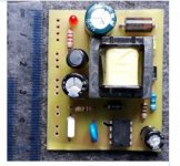
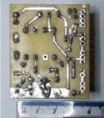
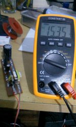
AUX SMPS 172.jpgAUX SMPS 173.jpgAUX SMPS 171.jpg

View attachment smps 2k-2 aux.pdf
 

expressel

New member
I meaned that but from 320V instead


Silvio

Well-known member
Yes I know that this could only have an inductor but then you will need an external mosfet. Also dropping down the voltage from 320 to 15 or 20v is rather high and extra care in design should be taken. I usually see this type of buck converter in smaller amplifiers where the current is small.
 

expressel

New member
I will try because I have good experience with buck convertors. You are dropping many volts but its not linear, its PWM.
 
Last edited:

Silvio

Well-known member
I bought some of these in fact and its true they are cheap. I could not bring the voltage more than 15v. I do not know the schematic of these either and I was afraid that the feedback winding supplying the IC will overload it if I had to rise up the voltage more than that. In my case the chip works off 320v directly so there is no problem about the set output voltage.

In my aux the peak voltage of the small buck converter rises up to 32v so the output can be risen to over 20v if wanted. The power will always be 8 watts . The current rises and falls according to the output voltage so that 8w can always be drawn from it.

The supply is meant for smps aux and this can be enhanced also to work with the power shutdown in conjunction with over current. However an NPN transistor can be added to the circuitry this will have the collector and emitter across the zener. when this transistor is switched thus shunting the zener will bring the voltage down to around 5v. This will also shuts down the oscillator chip like the SG3525 etc as these have a threshold voltage which they start or stop operating. Keeping all this in mind this auxiliary supply was built to meet these criteria.
 

res_smps

Member
dear all,
I have tried both flyback and buck using TOP224, I got up to 450mA continuous for buck converter
please this PI's design idea (attached)
 

Attachments

  • di1_1.pdf
    17.4 KB · Views: 43

res_smps

Member
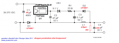
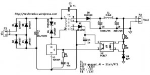
my schematic
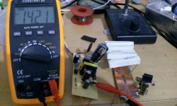
buck1.jpgtop224-buck1.pngtop224-fly2.jpgtop224flyback.jpg
note for buck :

tested up to 450mA, more than that excessive heat on the chip
1K5 resistor added to the output to prevent voltage surge
D1 & D2 should be of an ultrafast reverse recovery type (< 50 nsecs) and rated for 1.2 * VIN(MAX) and 3*Io

Silvio, sorry I did not mean to hijack your thread, because I'm not always online to manage my own thread.
I think you and other member can iuse this as a reference
 

Silvio

Well-known member
my schematic
Silvio, sorry I did not mean to hijack your thread, because I'm not always online to manage my own thread.
I think you and other member can iuse this as a reference

Its ok it is nice to share ideas among members. Now they have other choices for an auxiliary smps.
 

expressel

New member
dear all,
I have tried both flyback and buck using TOP224, I got up to 450mA continuous for buck converter
please this PI's design idea (attached)

Did you see Silvio? When using buck (flyback is not buck)(buck doesn't mean step-down) the voltage drop is big but Rds(on) is relatively small. Exactly that was my idea. res_smps tested and it gives 450mA which is good. You don't need to wind 135 windings. Just use buck for this little power.
 
Last edited:

blasphemy000

New member
These little ICs are great. I have a parts drawer full of recovered TNY26x and TNY27x DIP8 parts. The TNY parts are just different versions of the TOPSwitch ICs. I never thought of using one as a buck converter. It's not a standard use of the TNY ones, but it should work just the same.
As far as the normal use goes, the TNY ICs were specifically designed to be used as low power flyback converters using as few external parts as possible, and they work great. When it comes to the auxillary supply of a SMPS there is a good reason to go with the standard flyback design, and that is multiple output voltages, and the option of isolated voltage rails. The output doesn't need to be just a single voltage and it's very easy to add more secondary windings to get more rails. It's a very common use case for these controller ICs. Almost every PC power supply you take apart has a TNY26x/27x AUX supply with multiple output windings on the transformer. (Usually the +5Vsb rail which is earth referenced, and 1 or 2 mains referenced rails to run the main controller ICs.) It all depends on what type of supply you need and how much flexibility is required.
I think the only issue with using a buck converter would be the huge voltage step. For example going from 325V down to 15V would have a duty cycle of less than 5%. Some controllers might have issues delivering full power with such a small duty cycle. You'd have to test the design if you used parts other than what was verified by res_smps.

- Brad
 

norazmi

diysmps Senior Member
i did TNY because this chip has internal protection, overvoltage, short circuit, over temp, soft start.. etc... and its very easy and its regulated, ill post pic when im get back soon, now im outstation for a week, for now i just order pcb prototype from jlcpcb because its very cheap and save my time. you can adjust the voltage only by changing zener diode on feedback thats all... :D
 
Top