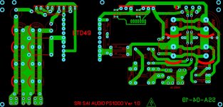
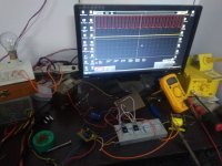
1000w smps based on LUDO3232

Silvio

Well-known member
Hi mituadas, the waves look ok to me it is only the little oscillation you have on the switch off at the bottom of the wave form. This can be corrected by putting a 4.7k resistor from gate to source. The resistor will help the mosfet to stay off between each cycle and any stray inductance and capacitance will not false trigger them. A snubber across the primary will also tame down the spikes. Do not be fooled as the more load you add to the output the spikes will get larger. you will correct this when the smps is stable.

I see you have an owon scope and this can work on battery. It is important that during the test you work on battery power so that it will be galvanically isolated from the mains. If your scope can handle 300v in the input you can directly connect the probe across the transformer primary with these set to X10. If not you can make a resistive divider across the primary of the transformer to limit the voltage for the scope. The resistive divider can be made with a 100k and 10k resistors in series. These will divide the voltage seen by the scope by 10.
Important that your scope probes will be put across the 10k resistor. Use only one probe and ground

Now you can measure the wave form across the primary of the transformer and see the real result,

It is important that you put a 100w lamp in series with the mains supply as a current limiter. Do not try to operate directly from the mains without a current limiter lamp. if something is not right you will blow the mosfets again.

You will only remove the 100w lamp if the smps is stable after 5 minutes of operation and nothing gets hot.

See how it goes from here and we talk later on your findings

Silvio
 

mituadas

New member
Hi Silvio

Thanks for your good advice.

Today I have tested my SMPS using 100W bulb in series. It was OK. I got 46-0-46 v output without any load. I have tested it for 1 minute. MOSFETs are without heatsink but no such heat observed in any components. Can I switch on without series ?? How much voltage i should get at output?My transformer is as per your design mean primary 11+11 and secondary 7+7 in ETD 49. Frequency is 62Khz.

Thanks once again

S Das
 

Silvio

Well-known member
Hi Silvio

Thanks for your good advice.

Today I have tested my SMPS using 100W bulb in series. It was OK. I got 46-0-46 v output without any load. I have tested it for 1 minute. MOSFETs are without heatsink but no such heat observed in any components. Can I switch on without series ?? How much voltage i should get at output?My transformer is as per your design mean primary 11+11 and secondary 7+7 in ETD 49. Frequency is 62Khz.

Thanks once again

S Das

Hi Das well it looks ok till now. Did you observed the waves across the transformer? They should be nice and square. Use the resistive divider I told you and take a look. It will be noticed that when loading the smps if there are any kind of spikes they will show more with load.

do not forget to put heatsink before loading the smps as the mosfets will heat up.

Regarding the output voltage you can calculate like this:- The half bridge voltage is around 155v at 230vac input.

So 155v / 22turns in primary = 7.05 volts per turn. Round off for 7 volts per turn.

for 7 turns secondary then multiply 7v X 7 turns = 49v.

The Peak no load output will vary according to the input voltage and you have to make a little allowance for the voltage drop in the output diodes etc.

The output voltage will drop with load to around 10% to 15% depending how good is the coupling in the transformer winding and also the mains input and flux density. Your output at full load of 300w or so will be more or less 46v/ 1.15 (15%) 40v. Do not worry much about this as when fitted with the amplifier it will not drop that much as the amplifier will not have a constant load and the voltage drop will be much less.
 

mituadas

New member
HI Silivio

I forgot to ask you one think that when i was testing my SMPS in series, 100W bulb was glowing till i switched off. Any mistake or it is normal? My scope model is PC based VDS1022 which can take maximum 40v input.

Thanks

S Das
 
Last edited:

Silvio

Well-known member
IF the lamp is glowing its not good it should stay off after start up with no load. Check that you are running a good frequency at least 65Khz or more. The lamp should glow at start up and then it should come off, Try to increase the frequency until the lamp will not glow.
If you are in excess of 85 or 90khz and the lamp still glows it means that you have something wrong in the transformer winding or somewhere else
 

mituadas

New member
Hi Silivo

For testing I have detached Transformer from PCB after that i tested with series again bulb is glowing. After that i remove PWM board then also bulb is glowing ,at last i remove mosfets then bulb turn off. I have tested mosfets using it is ok. Can you please analyse and let me know what to do next?

Thanks

S Das
 

Silvio

Well-known member
Hi Silivo

For testing I have detached Transformer from PCB after that i tested with series again bulb is glowing. After that i remove PWM board then also bulb is glowing ,at last i remove mosfets then bulb turn off. I have tested mosfets using it is ok. Can you please analyse and let me know what to do next?

Thanks

S Das

Can you post a picture of your pcb. I would like to see it. See that it is large enough so that I can follow the traces.
 

mituadas

New member
Today I add 10K register at Source to Gate of Mosfet. after that i connect mosfet and it was ok without PWM board and Transformer. Then i connect PWM board and bulb glow continuously. Then i connect Transformer and found output put voltage +44 and -44.

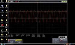
I took this wave form at Transformer.Which is not proper as per me.Please guide me how to improve.
Wave at Trafo.JPG
 

Silvio

Well-known member
Today I have tested my SMPS . Wave form taken from Mosfet attached. Please guide me what is the issue.

View attachment 6949

That is not a proper wave form it must show a square wave. Power up only auxiliary supply and check wave form. If it is not square then either sg3525 or IR2110 is not good. Try changing SG3525 first.

Buy genuine parts otherwise you will be disappointed.
 

mituadas

New member
Thanks for quick reply Silivio
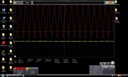
My wave form without main power on is very good. But after switch on main power i am getting this type of waves at Mosfet. I have removed transformer also still I am getting this type of wave.

Please clarify setting of Oscilloscope marked in red no 1 and 2.

Wave at Trafo-2.JPG

Thanks

S Das
 

Silvio

Well-known member
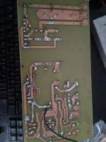
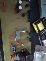
Hi Das, I think you may be doing something wrong. Post a picture of your PCB From top and also from bottom. I need to see what you done. Post also a picture of the waveform without main power.

The scope is showing what it should show. It is where are you putting your probes that matter.

Try to put a couple of turns with a piece of enameled copper wire around the transformer core on top of all other windings. Put the scope probes on the ends of this loop. The loop around the transformer will provide a safe voltage for your scope and it will be totally isolated. This is another way to check your waveform.

Please do as I tell you otherwise I cannot help you.

Capture.jpg

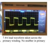
This is what the waveform should look like.
 

mituadas

New member
Thanks Silvio

Please find attached pictures. Now I am removing some parts from PCB to check Individually.

PCB-19-05-2019-1.JPG

Bottom.jpg

Top.jpg


Regards

S Das
 

mituadas

New member
Hi

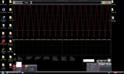
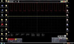
Today I have test with temporary setup my SMPS with 35V power supply.Every thing works well. Attached wave form for your reference.

Again i connected with 230v then same issue bulb is glowing.

Regards

Samarendra Das

test with 40v.JPG

IMG_20190523_215454.jpg
 

Silvio

Well-known member
Hi Das As I can see from the photos you sent that the waveform is getting on top of each other. Once you get this distortion it will not oscillate properly and the transistors will try to switch on at the same time. This is making your lamp glow, if you take it out then boom goes your mosfets.

I think there may be a problem in the transformer. See if you can find a transformer from an old computer power supply and try with it. Keep in mind that if the waves get disturbed from the IR2110 so does your waves at the gates and output waveform. Did you try to change sg3525 and also IR2110?

You can also try some decoupling on the oscillator PCB. Put 104 capacitor (100nF) between 12v supply feeding sg3525, solder it from the copper side directly with the legs of the IC. Put also gate source resistors 4k7 ohms.
 

Silvio

Well-known member
Hi Das i think your problem is that until you are testing you should ground pin 10 of sg3525 and not leave it open. This is very sensitive and any interference may cause it to partly trigger your shut down and disturb the waveform.
 

mituadas

New member
Hi Silvio

Thanks for giving suggestions. Finally I got the success. Only problem i was using 12v from a PC SMPS. for 12v i used one small transformer then every thing fine. I also tested in series and direct connection.Results are good. But while switching off the the SMPS i am getting a TIK sound from Transformer. I have test only 100W ouput, I will try to put more load and let you know.

Regards

S Das
 

mituadas

New member
Now my SMPS is working fine.Can anybody please guide me after rectification of 220V which one is better option for Half bridge SMPS using two 4 capacitors of 1000uf/250v or 2 capacitors of 680uf/450v.

Regards

S Das
 

Silvio

Well-known member
Now my SMPS is working fine.Can anybody please guide me after rectification of 220V which one is better option for Half bridge SMPS using two 4 capacitors of 1000uf/250v or 2 capacitors of 680uf/450v.

Regards

S Das

With 4 capacitors of 1000uF /200v you will have a value of 1000uF across the 320v line with 2 capacitors 680uf/400v you will have a value of 1360uF across the 320v line. 680uf will have more capacitance. You will need 2 divider capacitors 2uF/400v to divide the 320v rail.
 

mituadas

New member
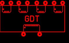
After successful project of Half bridge SMPS 1KV I am going for net project Full bridge 2KV. One doubt is whether to use IR2110 or GDT for mosfet/IGBT driver. I do not have knowledge on GDT. Can any body guide me how to make(Core/wire size/Turns) GDT as per below picture.

Thanks

S Das
GDT.JPG
 
Top