Hey all! I'm wanting to build this car smps (see link below), but it's not going to be use in a car. In fact, it's probably just going to end up powering an audio amp I built. Mostly though, the entire point of this project is for me to learn more about some higher powered switching supplies building techniques (while at a relatively "safer"-) voltage level) before going on and building one that can be plugged directly into the wall.
This is the site where I am getting the schematic from: http://sound.westhost.com/project89.htm
And these are some quick links to the two schematics i'm looking at:
http://sound.westhost.com/p89-f9.gif
http://sound.westhost.com/p89-f1.gif
I prefer to combine the two so that there is the output voltage adjust circuit as well as leaving out the Q1-Q4 driver transistors as they (according to the site) are apparently not essential because the SG3525 can source/sink enough current to drive the mosfets.
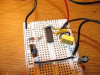
Now here is where i'm running into some problems. I have been breadboarding the driver circuit from Figure 9 for two days now trying to make it work and it just won't budge! Here are some of the changes I made. Keep in mind that when I finish this thing, all the part values will be correct. Just for initial breadboarding purposes are some of the components changed. I am powering this right now through a variable bench supply @15vdc.
-IC is a UC3525AN...according to the datasheets, there is no difference between the SG and UC version besides who manufactures it, but it was worth mentioning just cause i didn't use the "exact" IC
-R7,9,10: They are all 15K instead of 12k..I couldn't find for the life of me any 12k's in my parts bin.
-R8: 25 ohm...I know it's lower but it will still put the dead time on the output
-C11: 47uF but that shouldn't matter as it's a start up timing capacitor
-I didn't want the remote turn on/off feature so i removed R11, R12, C18, Q1, and grounded the shutdown pin.
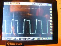
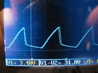
I double checked every single connection with my ohm meter when I placed the parts to make sure that things were connected correctly. Everything seemed perfect but when I applied power, no output showed on the oscilloscope for either out A or out B! I checked all my connections once again and yep...still nothing on the output. So i tried removing the ground connection on pin 10...same result. I tried a 15k pull up resistor to VCC on pin 10 and still no pulsing output. Then I thought it might be the chip that was broken so I replaced that too and tried the same things with pin 10 as before. Same result. ::SD I know this thing works as Rod Elliot does NOT post circuits on his website that he has not already tested himself. Does anybody have some suggestions for me?
Thanks,
Codex653
This is the site where I am getting the schematic from: http://sound.westhost.com/project89.htm
And these are some quick links to the two schematics i'm looking at:
http://sound.westhost.com/p89-f9.gif
http://sound.westhost.com/p89-f1.gif
I prefer to combine the two so that there is the output voltage adjust circuit as well as leaving out the Q1-Q4 driver transistors as they (according to the site) are apparently not essential because the SG3525 can source/sink enough current to drive the mosfets.
Now here is where i'm running into some problems.
I have been breadboarding the driver circuit from Figure 9 for two days now trying to make it work and it just won't budge! Here are some of the changes I made. Keep in mind that when I finish this thing, all the part values will be correct. Just for initial breadboarding purposes are some of the components changed. I am powering this right now through a variable bench supply @15vdc.-IC is a UC3525AN...according to the datasheets, there is no difference between the SG and UC version besides who manufactures it, but it was worth mentioning just cause i didn't use the "exact" IC
-R7,9,10: They are all 15K instead of 12k..I couldn't find for the life of me any 12k's in my parts bin.
-R8: 25 ohm...I know it's lower but it will still put the dead time on the output
-C11: 47uF but that shouldn't matter as it's a start up timing capacitor
-I didn't want the remote turn on/off feature so i removed R11, R12, C18, Q1, and grounded the shutdown pin.
I double checked every single connection with my ohm meter when I placed the parts to make sure that things were connected correctly. Everything seemed perfect but when I applied power, no output showed on the oscilloscope for either out A or out B! I checked all my connections once again and yep...still nothing on the output. So i tried removing the ground connection on pin 10...same result. I tried a 15k pull up resistor to VCC on pin 10 and still no pulsing output. Then I thought it might be the chip that was broken so I replaced that too and tried the same things with pin 10 as before. Same result. ::SD I know this thing works as Rod Elliot does NOT post circuits on his website that he has not already tested himself. Does anybody have some suggestions for me?
Thanks,
Codex653