Jaooo Bocko svaka cast , krenulo jeStarting with populations off the PCB V2.1:
You are using an out of date browser. It may not display this or other websites correctly.
You should upgrade or use an alternative browser.
You should upgrade or use an alternative browser.
1kW smps project (based on MicrosiM design)
- Thread starter ludo3232
- Start date
That looks nice!Starting with populations off the PCB V2.1:
Thanks for the words of support!
I read the procedure for the first launch, the frequency setting and death time are a bit unclear to me, as well as how many A/mm2 is the coil load calculated?
If I wind the coils with thin enough parallel wires, or copper foil, and use IRFP460LC transistors, I can use 100khz frequency as well?
SG circuit adjusts operating frequency via trimmer resistor?
Example:
I need 1000VA for the consumer, I calculate for +-50V/10A= 100V and 10A secondary, current density 4A/mm2, the required cross-section of the conductor is 2.5mm2 and it would be copper lacquered wire with a diameter of 1.78mm. Of course, it is wound with a wire with a diameter of 0.1mm or 0.15mm with the required number of conductors twisted in parallel, due to the skin effect... If I use a wire with a diameter of 0.15mm, it is necessary to twist 141 wires for 2.5mm2 ...
If you were to use 0.1mm thick copper foil, you would need a width of 25mm, and that width easily fits on a coil of ETD49 with a safety margin of 3mm on each side of the tape...
When calculating the primary winding, a similar principle, or?
I'm writing this extensively, because through reading this whole topic I came across a lot of wrong writing and incomplete calculations.
I didn't notice that someone wrote how much the current load is per square mm of the coil?
Here I am, abbreviated version of writing
Last edited:
Silvio
Well-known member
As for calculating the current density my suggestion is as follows.
If the smps is intended for audio purpose then keep in mind that class AB amplifiers are around 60% to 70% efficient. So for 700w rms output you need 1000w from your smps. A class D amp is around 90% efficient hence you will need 800w or so for the same output.
Also one must consider that audio load is not constant and usually the smps is loaded intermittently hence the duty cycle is around 60 to 70% when the amp is running at full blast.
Another thing to consider is that an smps running at 60khz will refill the output capacitors 1000 times faster than a normal mains iron transformer. This is why we do not need much capacitance on the output compared with an iron transformer.
Coming back to the point of current density for audio my design is usually 7 to 8A per mm² at this current density when the amp is running at full volume the average current will be around 6A (100v@10A) so the real average current density will then rise to about 5A per mm².
For the primary winding you need to add 20% more to the current as smps is around 80% efficient.
Copper wire choice considering skin effect.
Up to 65khz you can use 0.5mm dia copper wire
For a higher frequency up to around 110khz 0.4mm is good.
You need to calculate the cross sectional area of a single wire than use multiple wires in parallel to get to the needed CSA.
Always find the CSA needed at full load than divide it by 7 or 8.
I hope this helps.
Silvio
Well-known member
Hi Bocko, I never used copper foil but If you have copper wire especially for the primary I think it is better. Just remember that the current in the primary is half that of the secondary. At 230v a consumption of 1200w is around 6 amps more or less.
In my 1000w smps I used an ETD49 core epcos N87 material. The switching frequency of 60khz using a b max of 1600 guass. My primary and secondary turns where the same for 80-0-80v. I had 18 turns for primary and 9+9 for secondary. The smps works very well and can keep 800w continuous. It can peak 1200w though.
I used 2 bundles of 4 wires 0.5mm twisted (8 wires) for secondary. This gave me a total of 1.56mm² .As for the primary i used a bundle of 4 wires twisted 0.5mm dia. I divided the primary in 2 sections making half of it in the bottom then I wound the secondary windings and finally the second half of the primary. On top of that i wound the auxiliary windings to power the preamp and fan motors.
You can have a look at my youtube channel and watch the video in the link below. Play the video from the beginning. It has very useful tips.
You can also check my blog post on diysmps regarding winding practices for smps and also making litz wire at home.
Last edited:
Hi there.
Nice thread.
I am busy with resonance smps for tube hybrid, it is a LCC because it is a supply for tube drivers and pre-amp.
How you do the feedback? because audio power amplifiers have a lot of fast transients because of music, the smps has
to stay in regulation and keep low output impedance . A current feedback is maybe fast enough but voltage feedback
I do not now.
Is a open loop just above resonance not a good option, then it works like a normal 50hz supply transformer
but then a lot smaller.
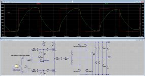
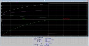
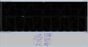
Pic is of a power amp resonance smps, 120 Khz switching 62 v 10 amp x 2 . See the resonance signal lags over the switching signal of
mosfets getting zvs. (full power) This is a need, so above resonance in all cases, I though for igbt who are current devices maybe you need
to go below resonance for zcs.
I did read a lot to get the hang of it a little, yes a little because it is quite complicated. the LCC in open loop however did a better yob keeping
voltage on track when amp draws high power.
regards
Attachments
Last edited:
Silvio
Well-known member
Hi Kees, I repair commercial amps everyday and rarely find a regulated supply. For an LLC supply using IGBTs at 120khz it is a must that it be zvs or zcs otherwise you will have problems with switching the gates and heat. IGBTs don't like high frequencies but when conditions are right they can deliver a lot of power.
If you really need a stable output I guess you better add a boost pfc stage.
In your case a smps that can deliver 1300 watts for audio is no big deal and need not be LLC. If you opt for the one on this tread you only need to use slightly better mosfets (25-30A) and you will get your 1.3kw with no problems.
Hi Silvio.
Thanks for your advice, I use a llc for the amp, it is build and working with mosfets and do 1 Kw
I bought these not build myself, just curiosity, Ali thing but see the mosfets are small isolated type..
The schematic you did see is for the tube driver/pre-amp part, this one does less wattage it only
give high voltages and the filament voltages, I did make it for some extra power so I can always
experiment with the amps.
The preamp part does 2 x 130 volts 0.25amp 350 volts 0.1 amp and 6.3 and 12.6 volts 10 amp.
only the low voltages are regulated, I use windings with midpoint to get these voltages and regulate only the 12,6 v.
System is a LCC or I can use a series resonance only, but that get quickly into LLC if I make a bad transformer, so
making one for SR is just use the leakage inductance. I do not need wide regulation for this tube supply.
As you mention, indeed a LLC open loop is the best way to go, I did test this on the resonance point or slightly above
to get a lagged transformer current so zvs occur like previous post picture. But for the tube filament voltages I need
to regulate.
PS newer igbt do much better on higher switching but Gan are also good ones.
regards
-
Silvio
Well-known member
Well opting for regulation depends on what chip is going to be your PWM controller. Just remember that the higher the output voltage the harder is to regulate the output voltage due to the need to scale this to a volt or so. The margin of error will increase due to the large difference. If then you decide to regulate the 12v than things will be simpler. How will all the voltages will hold when everything is working is another question.
My guess is to make a separate supply for the preamp and another for the main amplifier.
Good luck
My guess is to make a separate supply for the preamp and another for the main amplifier.
Good luck
Hi silvio,Well opting for regulation depends on what chip is going to be your PWM controller. Just remember that the higher the output voltage the harder is to regulate the output voltage due to the need to scale this to a volt or so. The margin of error will increase due to the large difference. If then you decide to regulate the 12v than things will be simpler. How will all the voltages will hold when everything is working is another question.
My guess is to make a separate supply for the preamp and another for the main amplifier.
Good luck
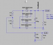
I do make two, one for the power amp 60 v x 2 and one for the tube preamp who have 350 volts 0.12 amp 2 x 120 volts 0.25 amp and 6.3 and 12.6 volts 10 amp (extra for be able to experiment with other tubes) I regulate the 12,.6 volts and the 6,3 volts is from halve that winding.
In sim it regulated fine. But the resonance tank (LCC type) is a current source, so I need to make Q such that it do the max power with some reserve and the pow power (for example when one tube breaks and load disappear, I need to make the right.
The high voltages are not regulated but do quite well, I can easily use a zener to make a over-voltage protection when load is open by whatsoever reason.. But I did see in sim that this voltage keep quite oke, because it is used for the tube grid supply voltage of 300 volts or 350 do not matter much. here it gets a different of 20 volts, and it is lower when open circuit.
I think a LCC is better for audio, fast regulation but als open loop is quite stable voltage under high load.
For LCC a voltage detector is needed, in case the load dissapairs, so feedback, only for the version for the tubes because of the HV.
Attachments
Last edited:
Hi all, I bought one of those 500 watt SMPS on Ebay from China and burned up the switching circuit. it is on a daughter board filled with glue and I was searching for a fix.
I just want to say the people on this board are the most helpful I have ever seen! Silvio and Microsim have helped the world learn SMPS. I watched a few videos today on youtube and thinking I might use the parts from the China SMPS and start over.
I just want to say the people on this board are the most helpful I have ever seen! Silvio and Microsim have helped the world learn SMPS. I watched a few videos today on youtube and thinking I might use the parts from the China SMPS and start over.
You can see the driver chip? or is these complete encapsulated.
I have a 1000 WATT version and did not yet use it but it does work, get nice 65 + 65 volts
and is 1 kilowatts, however the mosfet half bride is quite strange because it are mosfets
who are insulated, and small, that is quite scary I think, also with mine the mosfets and
the ic,s names are not readable.
But I can see the ic chip, and it is possible to measure out this chip, just look at the pins where the outputs are and the freq set pins
and feedback input pins and you will now.
desolder the small pcb and try to remove the resin of what is used. Most of the time when mosfet are blown,
the ic is also dead.
regards
I think its a resonant converter because of the 4 big capacitors. Yes, i blew the mosfets and the plastic control box went with it. Yes, completely encapsulated. I tried to take it apart but the glue was tough. it has a part number BHP500. I couldn't get anything out of it to measure. I never found an IC but a few transistors. I'm just going to use it as parts.You can see the driver chip? or is these complete encapsulated.
I have a 1000 WATT version and did not yet use it but it does work, get nice 65 + 65 volts
and is 1 kilowatts, however the mosfet half bride is quite strange because it are mosfets
who are insulated, and small, that is quite scary I think, also with mine the mosfets and
the ic,s names are not readable.
But I can see the ic chip, and it is possible to measure out this chip, just look at the pins where the outputs are and the freq set pins
and feedback input pins and you will now.
desolder the small pcb and try to remove the resin of what is used. Most of the time when mosfet are blown,
the ic is also dead.
regards
Hi 2pist
yes it is a resonance type of supply, for you I can look at what is used, possible i can find it with measurements or seeking pins, almost it is
a kwown cheap chip. Finding other mosfets is not so difficult, just look for ones wpecial for resoance with high breakdown voltages.
yes it is a resonance type of supply, for you I can look at what is used, possible i can find it with measurements or seeking pins, almost it is
a kwown cheap chip. Finding other mosfets is not so difficult, just look for ones wpecial for resoance with high breakdown voltages.


