sanumar001
New member
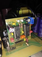
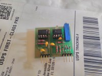
Why do not use a transformer instead of the GDT IR2110? .GDT Works more reliably and more easily customized.https://www.youtube.com/watch?v=EAVYDca-Hkk
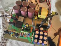
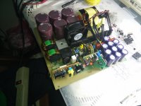
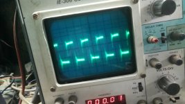
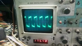
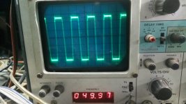
This is my smps 48v battery charger from the wind turbine.
This is my smps 48v battery charger from the wind turbine.