1kW smps project (based on MicrosiM design)

Jagd.Panther

New member
So I used the inrush limiter that you advised and now with about 1100W load connected, smps starts normally and I think It's good since My amplifiers protection takes about 2 or 3 seconds to connect the Subwoofers to amplifiers ouput
:UP:

I think now the protection set to about 15A at primary of the transformer since I can connect less than 2KW load without triggering the protection but not more than that
Is this good????
It's easy to estimate:

1st, calculate conduction loss for IGBT: Vce*Ice, according for 20A, 100degC Tj 2v*20 A= 40W.

2nd, calculate switching loss, (Ton+Toff)*Fsw at desired Ic , assuming you are using same Rg value as in the datsheet, you'll get 1.6mJ*55 khz=88W.

3rd, compare total dissipated power (^^^^ 1+2) taking into account derating factor (200W @ 100 Tc for FGL40N120AND, so 15A is safe).
 
:UP:

It's easy to estimate:

1st, calculate conduction loss for IGBT: Vce*Ice, according for 20A, 100degC Tj 2v*20 A= 40W.

2nd, calculate switching loss, (Ton+Toff)*Fsw at desired Ic , assuming you are using same Rg value as in the datsheet, you'll get 1.6mJ*55 khz=88W.

3rd, compare total dissipated power (^^^^ 1+2) taking into account derating factor (200W @ 100 Tc for FGL40N120AND, so 15A is safe).

Thank you so much for all your help
 

stewin

Member
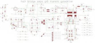
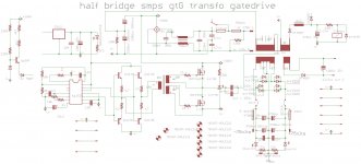
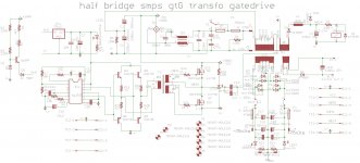
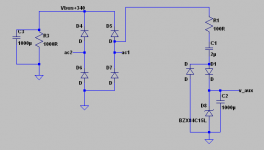
hi jagd .can i use your schema instead of tip 50 as a trigger to start up a smps which i use no aux 12 former??

my schema


diysmps.com 1kW smps project (based ...osiM design) - Page 118 soft-start.jpggtG self start smps.jpg
 

Jagd.Panther

New member
The soft start circuit I posted works with any kind of power supply, it's universal.

On your schematic the soft start circuit senses output voltage and is also OK. It's not needed to change it.

What is needed to be changed is:
- use full wave rectification for both AUX windings
- shunt both bulk caps with a resistor. Current through the resistor should be few tiems higher than leakage current of the bulk cap.
 

stewin

Member
thanks sir . i meant using your softstart 12vlts with 100r and 1uf schematic to start the smps , instead of using tip50 .
 
Last edited:

borysgo2

New member
badboy

Can You give me some help please.
Could You measure AC component at the output from yours SMPS at approx 30-50% load with 5ms/DIV please ?

I just would like see how does the ''mains'' ripple look like at the secondary side.

Big Thanks
 
badboy

Can You give me some help please.
Could You measure AC component at the output from yours SMPS at approx 30-50% load with 5ms/DIV please ?

I just would like see how does the ''mains'' ripple look like at the secondary side.

Big Thanks


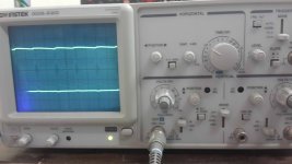
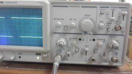
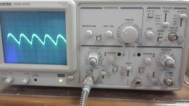
with about 540W load:
1.jpg
Secondary winding of transformer


2.jpg
3.jpg
output diodes


6.jpg
output DC ripple (50mv div)


** By the way the transformer that I used above is with 56-0-56V **
 

kaip

New member
The 100Hz ripple will always be presented at the output of any unregulated SMPS output.

However, that ripple can be minimized by adding Extra Capacitance at the output, for example 10000uF per rail.

Another option is to make the SMPS regulated witch is best option here, or to use a synchronized rectifier to LOWER the output ripple and increase the efficiency of the SMPS.


Hope that helps.
 

Jagd.Panther

New member
thanks sir . i meant using your softstart 12vlts with 100r and 1uf schematic to start the smps , instead of using tip50 .
It's possible with a minor rework. However I don't recommend using it to power up a PWM controller (use what you have on your schematic instead).
 

Attachments

  • v-aux.png
    v-aux.png
    7.7 KB · Views: 114

Jagd.Panther

New member
The 100Hz ripple will always be presented at the output of any unregulated SMPS output.

However, that ripple can be minimized by adding Extra Capacitance at the output, for example 10000uF per rail.
It's much much better to increase bulk caps capacity to deal with 100/120hz ripple . Speaking about energy storage (peak SMPS output) it's better to use 'bigger' caps on the primary side and not on the secondary side.
 

borysgo2

New member
badboy
Thanks a lot. That looks really good!!
How much of the uF you have at the primary side of the smps ??

I have 2x 680uF in series and with 300W I am getting around 4V of 100Hz ripple!! I must have something wrong.

THX!!
 
Last edited:

Jagd.Panther

New member
badboy
Thanks a lot. That looks really good!!
How much of the uF you have at the primary side of the smps ??

I have 2x 680uF in series and with 300W I am getting around 4V of 100Hz ripple!! I must have something wrong.

THX!!

300W @ 315v is ca. 1A.
2x 680uF caps in series give 340uF cap.
Ripple period is 10ms
Then voltage ripple would be (peak-to-peak) < 10ms * 1A / 340uF ~30V, or ~10%.
Caps on the secondary side obviously help with the ripple as well.
 
badboy
Thanks a lot. That looks really good!!
How much of the uF you have at the primary side of the smps ??

I have 2x 680uF in series and with 300W I am getting around 4V of 100Hz ripple!! I must have something wrong.

THX!!


you're welcome

I have 4x680uf on each input rails and 5x1000uf on output rails
 
300W @ 315v is ca. 1A.
2x 680uF caps in series give 340uF cap.
Ripple period is 10ms
Then voltage ripple would be (peak-to-peak) < 10ms * 1A / 340uF ~30V, or ~10%.
Caps on the secondary side obviously help with the ripple as well.

No I think he meant 2x680uf in parallel on each halve of the input voltage
 

borysgo2

New member
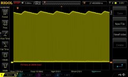
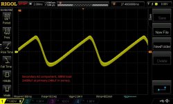
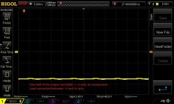
1.jpg2.jpg3.jpgI have 2x680uF in series at primary (eqivalent 340uF).
Trafo ratio is n=3. The secondary side capactance is 4x1000uF (2000uF per rail).
I am getting ripple at secodary side exacly 2.8Vp-p.

After adding another 2 caps 1000uF/200V at each rail (i have 840uF equivalent capacity at primary side), I am getting around 2,45Vp-p ripple at secondary (measured from V- rail to V+ rail).

badboy --> that is why I am so surprised that you have only around 100mV ripple at secondary (screanshoot no6 50mV/div).

I must do some more investigation at my board.
 
Last edited:

MicrosiM

Administrator
Staff member
View attachment 5616View attachment 5617View attachment 5618

I have 2x680uF in series at primary (eqivalent 340uF).
Trafo ratio is n=3. The secondary side capactance is 4x1000uF (2000uF per rail).
I am getting ripple at secodary side exacly 2.8Vp-p.

After adding another 2 caps 1000uF/200V at each rail (i have 840uF equivalent capacity at primary side), I am getting around 2,45Vp-p ripple at secondary (measured from V- rail to V+ rail).

badboy --> that is why I am so surprised that you have only around 100mV ripple at secondary (screanshoot no6 50mV/div).

I must do some more investigation at my board.


Its almost impossible to have 100mV of ripple at the SMPS output (Unregulated), I think there is some mistake in measurement's
 
Top