You are using an out of date browser. It may not display this or other websites correctly.
You should upgrade or use an alternative browser.
You should upgrade or use an alternative browser.
1kW smps project (based on MicrosiM design)
- Thread starter ludo3232
- Start date
@ MicrosiM
What do you think..? can i get full project of SMPS with IR2153?
You can start with this
http://www.diysmps.com/forums/showthread.php?149-Commercial-SMPS-using-IR2153D
Mhm .. Ok.. thanks..also i want to say that all project's from this site are only and strictly for my own personal satisfaction ..i will and i want to use this project's for supplying my DIY amplifiers..never for professional or commercial use..
Even if you use it for commercial use, there is no problem when say it.
Let me know if you still need help.
Hi MicrosiM ,
Can you please tell me,
1. what is the time delay in seconds required for bypassing the inrush current limiting resistors in sg3525 circuit.
2. which output of the sg3525 gives the first ouput pulse
regards ani
1. what is the time delay in seconds required for bypassing the inrush current limiting resistors in sg3525 circuit.
At least you need 3 seconds, then start SG3525
2. which output of the sg3525 gives the first ouput pulse
It should be output A
2. which output of the sg3525 gives the first ouput pulse
It should be output A
Hi MicrosiM ,
Thank you for the clarification.
In the 1Kw circuit if the output A of sg3525 is given to Low In of IR2110 , on the first pulse itself the bootstrap capacitor of IR2110 will get charged. so that there will be sufficient voltage accross the boot stap capacitor when the pulse at The Hin of IR2110 arrives.
regards ani
Last edited:
Hi MicrosiM ,
Thank you for the clarification.
In the 1Kw circuit if the output A of sg3525 is given to Low In of IR2110 , on the first pulse itself the bootstrap capacitor of IR2110 will get charged. so that there will be sufficient voltage accross the boot stap capacitor when the pulse at The Hin of IR2110 arrives.
regards ani
What does that supposed to mean in reality?
Hi MicrosiM ,
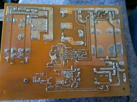
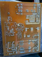
I was comparing Ludos ver2 pcb and ver3 pcb, interchanging SG3525 output pin avoids 3 jumpers in ver2 pcb.
This can be done if you keep both the Ic as per ver2 layout and integrating it to ver3 pcb keeping Mosfets and Transformer as it is.
It makes a symmetrical nice layout
regards ani
I was comparing Ludos ver2 pcb and ver3 pcb, interchanging SG3525 output pin avoids 3 jumpers in ver2 pcb.
This can be done if you keep both the Ic as per ver2 layout and integrating it to ver3 pcb keeping Mosfets and Transformer as it is.
It makes a symmetrical nice layout
regards ani
Hi MicrosiM ,
Is it not necessary to use a Gate to source resistor for MOSFETS ?
regards ani
You need that resistor when you use MOSFET!
@ microsim
hi again, can this design with SG+IR be used for powering my servo driver for DIY CNC machine? I need something about 800-1000W for my servos, and I would really would like to throw out that bulky toroid?
stay well...
specs of your servo?


