2x1000 W SMPS for audio

Sommer

New member
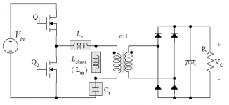
Hey I have plans about making a quasi resonant half-bridge 2kW SMPS
I would like to hear from you who have any good information that is nice to know when making such a converter.
I will make this project from now until december.
I already have some problems.
I would like the product to be used with both 100 VAC and 240 VAC without modifying anything inside. Do some of you know a smart way to sort this out?
Will it be possible to make a Half-bridge without voltage doubler or is it nessasary?
Please send any webpages you know that could help.
here is some specs:
Input:
100 - 240 VAC
50/60 Hz

output
+50 V 20 A
- 50 V 20 A

To be used for High end audio amplifiers so no EMI and RFI and no ripple on the output.
(No is equal to as as little as possible).
 

Sommer

New member
Also if anyone had som equations that could be used to calculate my own SMPS.
It's more the switching frequency i am interested in.
What is the highest Switching frequency i can get and still be able to keep the other specs?
 

Sommer

New member
I started to find a voltage detection circuit to control the 100 VAC to 240 VAC.
But i couldn't find any so now i have made some new ideas of solving the problem.
So if it is for 110 V then just parallel the two primary windings and if it is 220 V then change so it is in series.
What do you think about that idea? Do you know if it is possible to do it like this?
Dont look at the values those have nothing to do with a smps.
 

Attachments

  • Schematic Prints220.pdf
    11 KB · Views: 952
  • Schematic Prints110.pdf
    11.1 KB · Views: 567

giololucas

New member
I started to find a voltage detection circuit to control the 100 VAC to 240 VAC.
But i couldn't find any so now i have made some new ideas of solving the problem.
So if it is for 110 V then just parallel the two primary windings and if it is 220 V then change so it is in series.
What do you think about that idea? Do you know if it is possible to do it like this?
Dont look at the values those have nothing to do with a smps.

Easy way to do 110 to 220vac is using a manual switch with a voltage doubler.
 

MicrosiM

Administrator
Staff member
another option is an auto sensing circuit that will trigger a relay to start the voltage doubler mode, without doing any thing indeed ;)

In the 110V AC mode voltage doubler ON, in 220VAC mode voltage doubler oFF

but you still need to find a way to switch your AUX supply transformer from 110 to 220 and vise versa, other wise a small SMPS will do the JOB!
 

MicrosiM

Administrator
Staff member
At first you asked for something auto.

Now if you want it manually its another thing.
 

Sommer

New member
Yes because i read somewhere that a voltage doubler would lower the output when a load is applied

"A voltage multiplier is a specialized rectifier circuit producing an output which is theoretically an integer times the AC peak input, for example, 2, 3, or 4 times the AC peak input. Thus, it is possible to get 200 VDC from a 100 Vpeak AC source using a doubler, 400 VDC from a quadrupler. Any load in a practical circuit will lower these voltages. "​
This is from allaboutcircuits.com
So i thought that if i could use that detection circuit a relay could change the state. In that way i could limit the component number.
That's my thoughts

And every time something is applied there will be some loss.. that's what they tell us at the university.
 

giololucas

New member
Yes because i read somewhere that a voltage doubler would lower the output when a load is applied

"A voltage multiplier is a specialized rectifier circuit producing an output which is theoretically an integer times the AC peak input, for example, 2, 3, or 4 times the AC peak input. Thus, it is possible to get 200 VDC from a 100 Vpeak AC source using a doubler, 400 VDC from a quadrupler. Any load in a practical circuit will lower these voltages. "​
This is from allaboutcircuits.com
So i thought that if i could use that detection circuit a relay could change the state. In that way i could limit the component number.
That's my thoughts

And every time something is applied there will be some loss.. that's what they tell us at the university.

Hello Sommer.
Voltage drop is true in voltage doubler or other circuits with load.
I´m doing a smps which uses a voltage doubler, you can use this practical results to evaluate if it´s a good choice for you.
At 850W load in secondary (this means about 1000W or more in the entry of smps) the voltage drop was about 10 Volts.
150 V no load, 140V 850W loaded.
You can see movie and pics in the thread 800W smps for audio amplifier.
 

Attachments

  • DSC05314.JPG
    DSC05314.JPG
    22.7 KB · Views: 76

Yosemite

New member
It looks that the only solution to your problem is the Power Factor Corrector, witch is the best solution you may have!
 

Sommer

New member
Simulation

Hey everyone.
Now i figured out the requirements for powersupplys.
And if i take more than 200W from the AC in the Building i need to have a PFC added.
because if not, i would pull very high peak currents. With a PFC i would pull a more even current. (a bit hard to explain) but i hope you understand.
But there is something i dont know for sure.
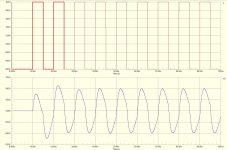
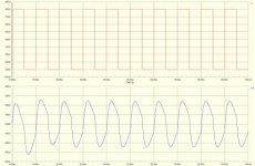
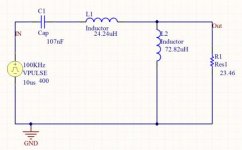
As you can see on the pictures i have added the supply is +- 400 V from the PFC (supply).
And another is from 0 to 400 I dont know what is the right.
And with the given inductors and capacitor i will get a sort of sinusoidal output.
If you have any advises of hints please let me know =)
 

Attachments

  • testafsimulering.JPG
    testafsimulering.JPG
    181.3 KB · Views: 78
  • Hele system.PNG
    Hele system.PNG
    17.2 KB · Views: 128
  • Simulering.jpg
    Simulering.jpg
    19.3 KB · Views: 65
  • SMPS.jpg
    SMPS.jpg
    13.6 KB · Views: 72
0-400 is right. There are specific ic's for active pfc there are even some threads in thei forum about it have alook around
 
Top