600/800W 220~230v AC Inverter SMPS from 12v DC

rezacadet

New member
Hi,
I am new in this forum. I am looking for a 12 v DC to 220~230 v AC 600/800w SMPS Inverter for Home appliance use like ips. I am looking all around the web for this kind of device but not getting clear answer. Please anybody help me providing full diagram and PCB layout.

Thank in Advance
Reza
 

DCPreamp

New member
Schematic you'll like!

Hi,
I am new in this forum. I am looking for a 12 v DC to 220~230 v AC 600/800w SMPS Inverter for Home appliance use like ips. I am looking all around the web for this kind of device but not getting clear answer. Please anybody help me providing full diagram and PCB layout.

Thank in Advance
Reza

Hi rezacadet,

Attached is a schematic very similar to what you're looking for! But, the schematic is for a 2,500W, 110VAC design. If you think this might work, you'd have to analyze how it works so you understand how to safely and effectively build such a complex project. Next, you'd have to scale it down to suit your lower power needs (unless you could use that much power!). Then you'd have to adjust the secondaries and capacitors to produce the higher voltage requirements of 220VAC (for 110VAC, the DC requirements are about 165VDC and for 220VAC you'd need about 330VDC). Lastly, you'd have to scale-up the power 'H' bridge to deal with the 330VDC modulating it to 220VAC. By the way, the IC chips used in this design are SG3525 or SG3526 push-pull driver chips. Also attached is a picture of the inside of the commercial product.

And while I did happen to have a schematic for such a powerful DC-to-AC converter, I do not have a circuit board layout for the project. Of course, since it will need some modifications to better suite your needs, you'd have to do some redesign anyways.

I do have concerns about somebody building such a complex, potentially dangerous project with limited knowledge. Hopefully you have advanced knowledge of safety protocols and building such projects, but since you asked for a PCB design too, I suspect not.

In any case, you will need to do some research in order to make this project work. It is not a very good beginner project given it's component count, need for so many transformers, the extremely high current nature of delivering 2.5KW from just 12V in, and last but not least, the highly dangerous and potentially fatal nature of 330VDC!

So, take a close look at the attached schematic and see it the project seems reasonable. If not, you're on the right web-site for information! Just begin detailing your project and start asking questions on this forum for the parts of the project you don't understand. I'd be happy to help you along, but you'll have to do the work and make the investment into the project.

Best of luck to you!
 

Attachments

  • 12V-120VAC Inv_Sch.pdf
    65.6 KB · Views: 1,137
  • 12V-120VAC Drvr_Sch.pdf
    34.7 KB · Views: 809
  • aims 2.5kw inside (600 x 450).jpg
    aims 2.5kw inside (600 x 450).jpg
    92.1 KB · Views: 482

DCPreamp

New member
Another converter topology to consider...

So, what do you think? Is this something that will suit your needs and you think you can build? It is fairly complex, but offers excellent performance and is standard in industry for DC to AC conversion at very high power levels. It is silent, light (relatively), and go up to 10+KW.

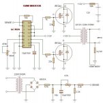
However, after thinking about your request for a while, I believe there is a much simpler way to achieve your goals. Attached is another circuit diagram that is much simpler, can be scaled up to 600/800W, 220VAC as you requested, but is noisy and less efficient. This schematic is a 150W design, but, like UPS systems, can be scaled up into the multi-KW power levels.

To scale this supply up to your power levels, you'd need about 6 MOSFETs per switching phase, a FET driver to overcome the input capacitance of 6 FET gates per phase, you'd need a 220VAC to 12VAC CT (center tap - very important! It must have a center tap for a push-pull design), 50/60Hz, 1KW (or more) power transformer (can be IE type or toroid), and the necessary wiring, PCB, etc. You could also use 2 transformers rated at 500W each if you can't find one with a center tap. This could make the transformers cheaper and easier to get. Basically you'd run the two primary's in series (forming a CT) and the two 220VAC secondaries in parallel.

Basically all this circuit does is take the 12VDC from the batteries, "chops it up" (switching) at 50 or 60Hz (depending on your local power grid), and feeds it into the transformer's secondary. The transformer then, through magnetic coupling, transforms the low input voltage (at very high current) into your required 220VAC (at lower currents). But, because you are switching the 12VDC into a square-wave, the output signal is pretty noisy and requires some filtering. It's also a noisy system (you can clearly/loudly hear the 50/60Hz hum produced) but depending on the appliance you're operating, you may not notice it anyway.

Same precautions apply here. Use extreme caution dealing with high voltages. Also, on the primary side of the system, as well as the system I previously described, you are dealing with VERY (like 100+ amps!) high currents that will require very beefy wiring, super thick traces with additional copper wire added to support the currents, and lots of capacitance (like 100,000uF or even 1/2Farad (like a car audio "super-cap")/16V) to filter the 12VDC.

Same thing applies here also - if you're going to attempt this project, ask lots of questions on this forum and document your project as you go so that you don't make major mistakes. There's no shame in asking for help. You can be more proud of a successful project that works and you asked lots of questions than to not ask questions and your project blows up in your face or destroys your microwave.
 

Attachments

  • DC-to-AC Inverter_150W.jpg
    DC-to-AC Inverter_150W.jpg
    40.2 KB · Views: 488
Top