BatoMM amp : LM3886 bridge amplifier with external feedback by macolakg

SR-been

New member
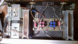
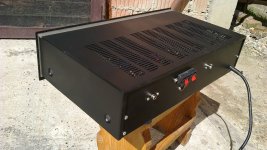
this is one of interesting amplifiers that you haven´t done yet and probably never heard one like this. its designer (macolakg) says that this is nothing new in measuring instruments but not quite often used in audio-amplifiers.

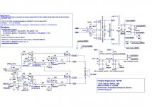
the external feedback is connected to a speaker terminal and it corrects all losses made in the way from amplifier output to a speaker connectors (relay contacts,bad insulation,capacity-inductiity losses...) and improoves sound greatly. that will be shown in a video a few post later.
 

SR-been

New member
here are the files needed to build this amplifier:

(in ZIP file there is all needed,along with sprint6 file)
 

Attachments

  • Bato MM jpg.JPG
    Bato MM jpg.JPG
    139.6 KB · Views: 128
  • Bato MM plocica toner.pdf
    113.8 KB · Views: 75
  • Bato MM raspored foto.pdf
    65.9 KB · Views: 67
  • jpg.JPG
    jpg.JPG
    428.9 KB · Views: 80
  • LM most No2.zip
    877.6 KB · Views: 95
  • social group.JPG
    social group.JPG
    108 KB · Views: 42
  • social group raspored.pdf
    12.9 KB · Views: 50
  • social group toner.pdf
    21.9 KB · Views: 51

SR-been

New member
the externall feedback is tested by using two 1mm iron wires betweeen amplifier output. the feedback wires are twisted from speaker terminals all the way to the connector on amplifier box. that is needed to improove its resistance to outside magnetic/electrostatic influence wich wouldn´t be great even if it was straight wire because it is low impedance feedback. that you can see when you look at the schematics-at the terminal it is connected to a speaker wires and on the other with 47R resistance. anyway twisted is better,and less job for correction circuit.

this would be the video:

[video=youtube;YaVux2K1Cq8]http://www.youtube.com/watch?v=YaVux2K1Cq8[/video]
 
Last edited:

SR-been

New member
and this would be the amp it self,first one to be enclosured and on pcb and second one ever builted - the first one was builted in point to point way from macolakg himself :)
 

Attachments

  • 2013-04-02-183.jpg
    2013-04-02-183.jpg
    129.7 KB · Views: 43
  • 2013-04-02-184.jpg
    2013-04-02-184.jpg
    110.3 KB · Views: 41
  • 2013-04-02-185.jpg
    2013-04-02-185.jpg
    77.9 KB · Views: 44
  • 2013-04-03-188.jpg
    2013-04-03-188.jpg
    132.5 KB · Views: 31
  • 2013-04-03-189.jpg
    2013-04-03-189.jpg
    131.8 KB · Views: 29
  • 2013-04-03-191.jpg
    2013-04-03-191.jpg
    72.5 KB · Views: 40
  • 2013-04-03-192.jpg
    2013-04-03-192.jpg
    142.1 KB · Views: 27
  • 2013-04-03-193.jpg
    2013-04-03-193.jpg
    133 KB · Views: 22

SR-been

New member
inside job:
 

Attachments

  • 2013-04-01-178.jpg
    2013-04-01-178.jpg
    354.2 KB · Views: 38
  • 2013-04-01-177.jpg
    2013-04-01-177.jpg
    336.7 KB · Views: 49

SR-been

New member
and this is the most important: firs BatoMM amp ever built and its stability at 8uF clear capacitance load
 

Attachments

  • 8uF_na_izlazu.JPG
    8uF_na_izlazu.JPG
    188.4 KB · Views: 35
  • 8uF_oscilogram.JPG
    8uF_oscilogram.JPG
    116.4 KB · Views: 29
Last edited:

SR-been

New member
if any questions,please ask... i can´ tell you all that would the designer would himself,but i will try. macolakg designed the amplifier,and i have drawn pcb by his directions.
 

SR-been

New member
if anyone wants ,here is protect+clip indication,one is with uPC1237 and another from ESP project33. the thing is that remote sense must be connected along with speakers,speakers can be connected without remote sense but not the other way around. so if you use external protection there must be a pair of relay connectors for ext.fb.

if you disconnect speaker from the amplifier and leave ext.fb. connected to the speaker terminals the current will flow through f.b leads and through 47R to a speaker and amp will see all the voltage at 47R as an error and it will try to correct it. the result will be burned 47R resistors,nothing will happen´ to a LM or LME ic´s.

that is why,if we use externall protection,we must have simultanious disconnection of speakers and remote feed-backs. the LM ic´s have protections of their own so externall protection is not really needed(macolakg suggests not to use it) but if you like to use it here are two versions to do it.
 

Attachments

  • BatoMM zaštite.rar
    829.1 KB · Views: 78
  • esp33 + clip.JPG
    esp33 + clip.JPG
    346.6 KB · Views: 41
  • ESP33+ clip oba bakar toner.pdf
    72.4 KB · Views: 55
  • ESP33+clip oba raspored foto.pdf
    52.5 KB · Views: 43
  • uPC2357 zaštita + klip indikacija bakar toner.pdf
    47.8 KB · Views: 65
  • uPC2357 zaštita + klip indikacija raspored foto.pdf
    32.5 KB · Views: 40
  • uPC + klip indikacija.JPG
    uPC + klip indikacija.JPG
    228 KB · Views: 37

SR-been

New member
in RAR file there are both protections and all the files needed,along with sprit6 files.

here is a schematics of clip indication done by our designer Mile Slavković known as APEX audio:
 

Attachments

  • APEX clip led.jpg
    APEX clip led.jpg
    35 KB · Views: 38

SR-been

New member
with a little math you can calculate at what voltage to speakers/power will led´s start to light up.
 

SR-been

New member
finally closed

this is how it looks at the end:i have taken out external protection and connected output and remote feedback directly to the output connectors,replaced front and painted cover and front. i have left APEX clip indication,this is how it looks and works at
the end:

[video=youtube;oQ3bTPmpGBM]http://www.youtube.com/watch?v=oQ3bTPmpGBM[/video]


it is a sad thing that there is no interest in this amplifier,it is diferent than anything that you ever heard and you would be probably pleasantly surprised if you heard it...
 

Attachments

  • 2013-05-18-567.jpg
    2013-05-18-567.jpg
    324.4 KB · Views: 33
  • 2013-05-18-572.jpg
    2013-05-18-572.jpg
    286.9 KB · Views: 38
  • 2013-05-18-576.jpg
    2013-05-18-576.jpg
    294.9 KB · Views: 18
  • 2013-05-18-577.jpg
    2013-05-18-577.jpg
    290.4 KB · Views: 22
  • 2013-05-18-578.jpg
    2013-05-18-578.jpg
    313.2 KB · Views: 20
  • 2013-05-18-579.jpg
    2013-05-18-579.jpg
    310.8 KB · Views: 21
Last edited:

smps_fan

New member
Hey that is a very cool amp dude ! I watched your videos and it sounds very clear and crispy ! I love your amp. I´m not so much online thats why I response late. But as I will have more time later I´m looking forward for your posts ! Keep your good work ! You have one more fan :) Best regards smps_fan
 

SR-been

New member
thank you all,audio DIY is my hobby and almost half of my DIY started as an idea on paper that people like Apexaudio,MacolaKG,dragan100...have given on our local forum. they got an idea,draw a schematic and than I draw a pcb, buy some parts and test it with modest equipment I have. many of those ideas have been proven in practice, these people know their ideas from rooth... lately I am working on an amplifier that first started as Sony preamplifier clone improved by Dragan100 and APEX, and realised by viktor1986. than came an idea to create an amplifier based on that schematics (preamp has really nice output square wave even at 150kHz!), so work is in progress now. it has separate supply of VAS,it is mosfet / bipolar hybrid output stage and it is expected to have really low THD even at 150W/8r load (simulator tina-ti). if anyone show any interest I will post another thread and files I have drawn (with a lot of help from friends named above).
 
Last edited:
Top