Best IR2153 design?

rcbuck

New member
I ordered a couple of IR2153D chips and a few high voltage Mosfets today to begin experimenting with a half bridge ~200-250W power supply. I have ETD39 cores and bobbins on hand so I will use them for the transformer. What is the best 2153 design on the diysmps site to use as a basis for design? Or is there a design somewhere in Google world that could be used as a starting point? I will be running the supply from 120 V line supply so I will use a voltage doubler to get the ~330V bulk supply.

In the initial design I am going to power the IR2153 with an external 15V power supply so I won't have to deal with start up issues and possibly blowing the 2153 and/or Mosfets. After I have the supply running I'll work out something to have it start from the bulk supply and delay turning the Mosfets on after a slight delay.

Any pointers or suggestions are appreciated.
 

MicrosiM

Administrator
Staff member
I ordered a couple of IR2153D chips and a few high voltage Mosfets today to begin experimenting with a half bridge ~200-250W power supply. I have ETD39 cores and bobbins on hand so I will use them for the transformer. What is the best 2153 design on the diysmps site to use as a basis for design? Or is there a design somewhere in Google world that could be used as a starting point? I will be running the supply from 120 V line supply so I will use a voltage doubler to get the ~330V bulk supply.

In the initial design I am going to power the IR2153 with an external 15V power supply so I won't have to deal with start up issues and possibly blowing the 2153 and/or Mosfets. After I have the supply running I'll work out something to have it start from the bulk supply and delay turning the Mosfets on after a slight delay.

Any pointers or suggestions are appreciated.
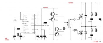

A good starting point is the YAMAHA SMPS based on the IR2153D chip, but this wont be your best choice of SMPS, as the IR2153D suffers from start up issues.

Check Ludo first SMPS, it was based on IR2153D, then he changed to SG3525.


If you need more help, Just Call


Good Luck
 

rcbuck

New member
Since I want to play with the IR2153D I will start with Ludo's first SMPs. I will avoid startup problems with a separate 15V supply. That is how Yamaha dealt with it. Once I get it going I'll see what I can do with the start up issue.

The SG3525 and IR2110 is a good combination. Unfortunately the IR2110 is expensive. Of course if it saves a pair of Mosfets I guess it is worth the cost.
 

MicrosiM

Administrator
Staff member
IR is simple

Since I want to play with the IR2153D I will start with Ludo's first SMPs. I will avoid startup problems with a separate 15V supply. That is how Yamaha dealt with it. Once I get it going I'll see what I can do with the start up issue.

The SG3525 and IR2110 is a good combination. Unfortunately the IR2110 is expensive. Of course if it saves a pair of Mosfets I guess it is worth the cost.


Start up issues with IR2153D is not related to the separated supply. Current sensing problems will be faced also.

It will be a good experiment playing with that simple chip :) , I made SMPS with it also, check here:-
http://www.diysmps.com/forums/showthread.php?38-MY-1KW-SMPS-Completed

You can use SG3525 with a GDT and all cheap and safer!


Good Luck
 

rcbuck

New member
You can use SG3525 with a GDT and all cheap and safer!

MicrosiM, do you have a link for a SG3525 with GDT circuit? I have several of those from old PC power supplies.

How would you calculate the GDT windings? My guess is I could probably use one of the driver transformers out of the PC supplies. I'm assuming that is what the smaller transformers are in the PC supplies. Since I am laying out the board for the IR2153 circuit I may as well lay one out for the SG3525 and make both boards at the same time.
 

MicrosiM

Administrator
Staff member
MicrosiM, do you have a link for a SG3525 with GDT circuit? I have several of those from old PC power supplies.

How would you calculate the GDT windings? My guess is I could probably use one of the driver transformers out of the PC supplies. I'm assuming that is what the smaller transformers are in the PC supplies. Since I am laying out the board for the IR2153 circuit I may as well lay one out for the SG3525 and make both boards at the same time.

Hello


Are you able to get some free samples of ferrite cores from
http://www.coilws.com/index.php?main_page=page&id=106

or any other alternative company in USA? the higher AL value is what you need from small toroidal cores

If not, it will take you some time trying and playing with those GDT taken from PCB SMPS.

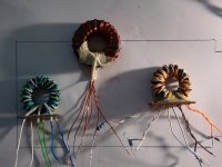
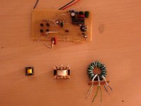
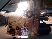
see schematic, and enjoy some pictures from my old tests..

GDT_Driver.jpgDSC01305.jpgDSC01464.jpgDSC01136.jpg
 

rcbuck

New member
Hello


Are you able to get some free samples of ferrite cores from
http://www.coilws.com/index.php?main_page=page&id=106

or any other alternative company in USA? the higher AL value is what you need from small toroidal cores

Yes, I have bought from them before. I have several small cores on hand here plus some high AL value toroids. I'll experiment and see what kind of results I get.

Thanks for the pictures and the schematic. They give me an idea of the turns ratios needed for the transformer. I'll unwind a couple from the PC supplies to see what ratios they were using.
 

MicrosiM

Administrator
Staff member
You will need 1:1 Turns ration into your GDT

Using any toroidal core with AL value higher than 5000 will work perfectly

If you need any help, just ask

Regards
 

rcbuck

New member
This is the schematic I am using to start my experimenting with the IR2153. It is a modified version of the Yamaha EMX5000. I'll start by leaving the output transformer and Mosfets off of the board. I'll feed 15 volts directly to the IR2153 through D3. Once I confirm the oscillator is running I'll apply enough voltage to the top of R14 to cause 5 amps to flow across it. Then I'll play with the values of R12 and R13 to cause the IR2153 to shutdown.

After the above tests are complete I'll put the output transformer and Mosfets on the board and apply about 50 volts through my variac, isolation transformer, and bulb and see what happens. For this test I won't have D3 connected to the aux winding. I'll still be applying 15 volts to the IR2153 through an external supply.

If anyone sees any potential problems let me know. I'm still working on the PCB layout.
 

renotrend

Member
Forgot to attach schematic.

hi rcbuck , i have make it SMPS using IR2153, ETD49 ,IRFP460 directli to mosfet (no BJT)with protect like yamaha design emx5000, i dont have problem with star-up. actualy in yamaha Protect circuit include slow star-up osc .it is Q116 and C136 .do you have schematic smps yamaha emx5000 ? you can see that

and short circuit is working .
 

rcbuck

New member
renotrend, yes I have the emx5000 schematic and my power supply is somewhat based on that. I am still waiting on a few parts to come in so I can build the supply. I will make the circuit board this weekend. When the parts come in I will start testing. I am only going to build the supply for 350 watts as that is all I need. I am still trying to determine how to put a 350 watt load on the power supply. It will put out +/- 35 volts.
 
Top