Boost converter for powering laptop(problems)

ytsoc

New member
Hello everybody,I,tried to build a dc-dc boost converter for powering my laptop in the car, so 12v to 19V.
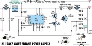
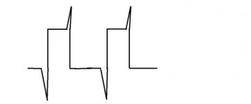
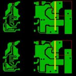
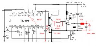
So i used this schematic, pcb layout and the signal on the mosfet drain looks like that.
Coil is made with an E+I core from a ATX PSU with gap appx 0.4mm.
Those spikes are aproximately 55v p-p and i reduced them to about 50v with a sunbber (100nF+4.7ohm).
What did i do wrong? is the pcb that bad that is causing these oveshots?
I almost forgot: the spikes are 55v p-p when i draw 1.6amps at output . They increase as i draw more current and obviously decrease if i draw less current.
Edit: added ext links to bigger pics
PCB
schematic
Spikes
 

Attachments

  • spike.jpg
    spike.jpg
    7 KB · Views: 34
  • asta1.jpg
    asta1.jpg
    15.9 KB · Views: 48
  • IEeZ5.jpg
    IEeZ5.jpg
    21.9 KB · Views: 91
Last edited:

ytsoc

New member
i doubt that, i tried multiple coils even pne of these but didn't get rid of spikes.
Mosfet is irfz44n ; diode mbr2045. Target current is 5-6amps.
Coil is made with 7x1mm wire. and has 23uH(measured)
 

wally7856

New member
Check your gate drive waveform at the gate. If that looks good then i would think the switching frequency is wrong for that inductor, because it sure looks like it is saturating to me.
 

ytsoc

New member
i see, the waveform at the gate lokks kinda ok(for a noob like me) Can you sugest a frequency?
I tried between 20k and 30khz, but to no avail.
The pcb looks ok?
 

ytsoc

New member
i increased gate resistor to 100 ohm and things got better but i still have a spike(only one now) .
Here is how it looks on the scope. 0-34sec drain waveform with minimal load and then drawing 1.5 amps.
34 sec -end waveform at gate same conditions 1.5amps draw.
Snubber 4.7ohm and 100nF. Freq aprox 70khz
[video=youtube;NypGr1r-teI]http://www.youtube.com/watch?v=NypGr1r-teI&feature=plcp[/video]
 

wally7856

New member
The gate drive waveform looks very bad but i am not sure why. It looks like you have something across the 330ohm resistor on base of gate transistor. I do not know why it is there. Also 330 ohms might be low, try up to 1k.

For now just try to get the circuit to switch properly. Try replacing the inductor with a 1k resistor. Now you do not have to worry about correct switching frequency or saturation.

Here is another similar circuit i found that has slightly different pin connections to TL494.
 

Attachments

  • tl494 2008108215556207.jpg
    tl494 2008108215556207.jpg
    41.1 KB · Views: 74

ytsoc

New member
i don't think you understand, the gate wave form can be seen at 1:00 time(pause there) in the video, it almost looks like a perfect rectangle, what is wrong with that?
The changes are the duty cycle variation due to me, connecting and disconecting a load.
 
Last edited:

ytsoc

New member
Fixed it, problem was gate diode and a faulty scope probe
[video=youtube;ecPlh2QNw0k]http://www.youtube.com/watch?v=ecPlh2QNw0k&feature=youtu.be[/video]
 
Top