Car SMPS Project

Hi bad boy well saturation will only occur if there is not sufficient number of turns,

What is keeping you to try the inverter at a higher frequency? Try that and see if there is the same effect.

If you have the same result I am afraid you have to add another turn to the primary winding

Silvio

Hi

actually the project I'm working on is from here but with some modifications I made
http://sound.whsites.net/project89.htm

higher frequency means lower flux density and lower power in the output and also if I want to add more turns in primary then I have to lower frequency as well (to even below 20khz), am I right?
do you have any idea what I'm doing wrong here? do you have any powerful inverter that can withstand this much power (around 1Kw)
 
can I go lower than 20Khz in frequency ao that I could go with 4+4 turns in primary??
doesn't this effect amplifier or produce any noise on it
 
@dear Silvio
Doesn't saturation only ralated to flux density?
Does it mater to have more or less turns on primary as long as you keep flux density the same by changing the frequency??
I did as you suggested and increase the frequency and thus lower gauss on transformer and then the transformer saturation goes away but the voltage drop is higher and no matter what I did I couldn't get more than 500W from the smps
 

Silvio

Well-known member
@badboy

Yes indeed the higher the flux density the better the magnetic field and the better output. Care must be taken not to exceed a certain limit as the magnetic field will collapse and the core will saturate.
I told you to raise the frequency so that to avoid saturation and as you noticed the magnetic field dropped also and less power was transferred.

I think you have a coupling issue here and it may be the case that 2 turns are not providing enough coupling with the other windings.
Another option for you is to make another turn or two in the primary so that you have better coupling. The flux density will decrease a bit but you can raise it again by creating a small gap between the cores. This will lessen the inductance again to the normal value for the frequency used.

It would be a good practice if you measure the inductance of the primary before dismantling the transformer so that you will know what is the value. By making a small spacer between the cores when the new winding is finished you can bring the same value or maybe a little higher than the present value with 2 turns. The small gap will also help the core to withstand more flux before saturation.
The secondary turns have to be adjusted according to the new primary turns so that you will have the same output voltage.

One last thing you should test before dismantling the transformer is to make a small gap (2 pieces of paper thick) on the three legs between the cores and run the smps at 40Khz and see what you get and see if it still saturate.

Regards Silvio
 
Last edited:
@badboy

Yes indeed the higher the flux density the better the magnetic field and the better output. Care must be taken not to exceed a certain limit as the magnetic field will collapse and the core will saturate.
I told you to raise the frequency so that to avoid saturation and as you noticed the magnetic field dropped also and less power was transferred.

I think you have a coupling issue here and it may be the case that 2 turns are not providing enough coupling with the other windings.
Another option for you is to make another turn or two in the primary so that you have better coupling. The flux density will decrease a bit but you can raise it again by creating a small gap between the cores. This will lessen the inductance again to the normal value for the frequency used.

It would be a good practice if you measure the inductance of the primary before dismantling the transformer so that you will know what is the value. By making a small spacer between the cores when the new winding is finished you can bring the same value or maybe a little higher than the present value with 2 turns. The small gap will also help the core to withstand more flux before saturation.
The secondary turns have to be adjusted according to the new primary turns so that you will have the same output voltage.

One last thing you should test before dismantling the transformer is to make a small gap (2 pieces of paper thick) on the three legs between the cores and run the smps at 40Khz and see what you get and see if it still saturate.

Regards Silvio

@Dear Silvio

So I place a gap in the core legs and it did help a bit but not a lot (I could get about 50W more in the output) and transformer still makes a click sound and voltage at output drops and mosfets at one sides of primary get really hot while the other side stays cool
I even increase the primary turns (4+4) and still the same result
Maybe it's my winding configuration????
I winded the 2 primaries winding clockwise and then the secondaries counter Clockwise
1---> 4 Turn of Primary
2---> 4 Turn of Primary
3---> 26 Turn of secondary
4---> 26 Turn of secondary
 

Silvio

Well-known member
@badboy

Well getting 1KW at 12v is not so easy because there is a lot of current involved (80 amps) losses tend to rise drastically. Having doubled the primary turns you can increase the gap to 1mm that is you make a 0.5mm gap between the 3 legs and see how it goes.

You would have been better off if you started with 24volts at least there will be half the current involved. I never made an inverter this big and I am trying to help you the best I could.

What I have seen from commercial inverters is that they use several cores like 2 or 4 cores then the output will be in series to get the voltage needed. The load this way will be divided between the cores and the each will see half or quarter the current depending on the number of cores in the setup.

Winding configuration is like this:-

first secondary winding start at pin wind 26 turns then center tap then continue from center tap and wind another 26 turns and finish at the other pin.
put 3 layers mylar tape

Primary winding start at pin wind 4 turns and then center tap . second half of primary start from center tap continue wind the second half 4 turns the same direction of the first 4 turns and finish at other pin

It is important that you wind the same direction either clockwise or anti clockwise. Try to fit windings in a single layer to help for good coupling.

Can you post some scope shots of both channels during load?

Regards Silvio
 
Last edited:
@badboy

Well getting 1KW at 12v is not so easy because there is a lot of current involved (80 amps) losses tend to rise drastically. Having doubled the primary turns you can increase the gap to 1mm that is you make a 0.5mm gap between the 3 legs and see how it goes.

You would have been better off if you started with 24volts at least there will be half the current involved. I never made an inverter this big and I am trying to help you the best I could.

What I have seen from commercial inverters is that they use several cores like 2 or 4 cores then the output will be in series to get the voltage needed. The load this way will be divided between the cores and the each will see half or quarter the current depending on the number of cores in the setup.

Winding configuration is like this:-

first secondary winding start at pin wind 26 turns then center tap then continue from center tap and wind another 26 turns and finish at the other pin.
put 3 layers mylar tape

Primary winding start at pin wind 4 turns and then center tap . second half of primary start from center tap continue wind the second half 4 turns the same direction of the first 4 turns and finish at other pin

It is important that you wind the same direction either clockwise or anti clockwise. Try to fit windings in a single layer to help for good coupling.

Can you post some scope shots of both channels during load?

Regards Silvio


Here you go

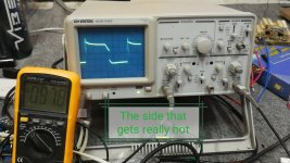
This pictures are from the side of primary that the mosfets connected to it gets really hot with high load :
Without any load :
Screenshot_20180619-134854.jpg
With 37.5 Ohms load :
IMG_20180619_135947.jpg

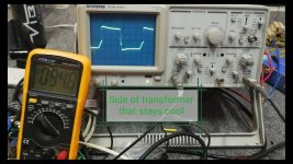
The other side of primary that stays cool:
Without load:
Screenshot_20180619-134854.jpg
With 37.5 Ohms load :
IMG_20180619_135455.jpg
 

Silvio

Well-known member
Here you go

This pictures are from the side of primary that the mosfets connected to it gets really hot with high load :
Without any load :
View attachment 6707
With 37.5 Ohms load :
View attachment 6708

The other side of primary that stays cool:
Without load:
View attachment 6707
With 37.5 Ohms load :
View attachment 6709

I want to know where are you putting your probe is it on the gate of the IGBT or the ptrimary winding?

The first picture shows a beautiful wave form the the custom sloping trailing edge of an IGBT switch. Is this the full output winding or the input?

The side that is getting hot shows a very disturbed wave form and that is causing the heating of the IGBTs.

Please post pics with the probes on the gates. The signal must be clean here otherwise you will never get a good waveform on the output.

As the topology you are using is push pull then you can switch the gate wires if you have not done a pcb yet.

As you can notice There is ringing at the disturbed wave form when the IGBT is fully switched on, You must use a suitable snubber to calm things down, The more load you draw the more ringing you will get. avoid long wires or traces to the gates and away as possible from high current paths. These are to be at 90 degrees to the current path where possible to eliminate coupling. A double sided pcb with a ground plane will isolate any stray inductances that may couple to the gate drive.

Check your dead time and set for at least 2uS this will give either transistors time to fully switch off before the next turn on. You can make it less after things will be stable. Try also a piece of screened cable to drive the gates to eliminate any stray coupling. Use a gate emitter resistor of 1k to eliminate any false trigger.

If all this will not help then it could be a case of symmetry in the input winding. Push pull is very specific and the primary has to be uniform and symmetrical as possible otherwise you will be in for surprises.

I will send you some pics later of a commercial inverter of 3kw???? (I doubt it) to see how they make the ferrite cores.

Please post pics of probe at the gates and also at primary winding. if possible use two probes at the same time so that I see both channels together. (one time at the gates and one time at the windings)

Regards Silvio
@ Dear Silvio

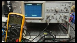
Here's a video clip from the Gate of mosfets at the same time according to Negative :
[video]https://youtu.be/na7jK3TaPWM[/video]

Here's some shots of the transformer primaries at the same time according to Positive :
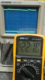
both channel is on 0.5 Volt/Div and X10 on probe.
21.jpg
22.jpg

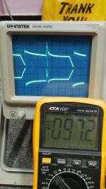
The same test with different Volt/Div for one of the primaries (the little one is the side that its mosfets gets hot):
11.jpg
12.jpg
The large Signal is on 2 Volt/Div and its probe on X10
The small Signal is on 0.5 Volt/Div and its probe on X10
 
Sorry about the previous video, there was a ground issue in the measurements
here's the right one :

[video]https://youtu.be/1-aT29eX7GA[/video]

Turn's out that the voltage pulses from one channel of the SG3525 is going low at high power (The one that drives those stone Cold mosfets)
So it's a drive issue, am I right???
 

Silvio

Well-known member
@Badboy

What you did not post is with the probes at the gates with the inverter on load. If you have a disturbed gate drive on load you will not get a good wave shape on the output. A bad wave form will cause heating of the IGBT
The pcb is confusing and you have a lot of links which are not shown.
Why did you position the igbt across? How are you going to fit the heat sink? Or you going to fit a flat heat sink under the pcb?
I see gate resistors and traces parallel to the high current paths these will couple stay inductance and disturb the wave form.
I suggest you put the sg and signal circuit on a separate pin header to lift it off the pcb for less coupling to the high current paths

Regards Silvio

the last video I uploaded was from the gates of mosfets at the same time
when I connect the load one side of primary's mosfets gate voltage drops and that is why it's stone cold and the other sides decrease a bit but that normal under load
why this happening??
buy turning the dead time trimmer clockwise or counter clockwise the mosfets that gets hot change position with mosfets on the other half of primary

I'm tempted to go with Full Bridge configuration instead of push pull
I think I can get more power out of a Full Bridge
 

Silvio

Well-known member
the last video I uploaded was from the gates of mosfets at the same time
when I connect the load one side of primary's mosfets gate voltage drops and that is why it's stone cold and the other sides decrease a bit but that normal under load
why this happening??
buy turning the dead time trimmer clockwise or counter clockwise the mosfets that gets hot change position with mosfets on the other half of primary

I'm tempted to go with Full Bridge configuration instead of push pull
I think I can get more power out of a Full Bridge

The reason for all this has to be found. Start tracing the signal where is it stopping. if its from the IC then try to change it, decouple the supply rail as closely as possible to the IC pins, Make a separate pin header and change pcb.

I am surprised how you manage to get 500w with only one side working.

Full bridge will be the same as push pull as far as power is concerned with the only difference that you will only have one primary of 12v instead of two and duty cycle on the winding will double.

the 500W is before the transformer saturation and is that situation all mosfets heat normal

Full brige does not suffer from staircase saturation and gives some forgiveness on how primary windings is winded
 
Last edited:

Silvio

Well-known member
the 500W is before the transformer saturation and is that situation all mosfets heat normal

Full brige does not suffer from staircase saturation and gives some forgiveness on how primary windings is winded

What can I say? well you need 4 fets for full bridge and 4 gate drives more complicated as it seems. If you are willing then try it see what happens.
 
@Silvio

I manage to build a 1kw converter with full bridge topology
I need to know what is the lowest voltage I should design the converter for when car is running?
as I measure the voltage before in car idle condition the voltage was around 14.7v without any load
so how much drop should I expect from a 90A alternator under high load?
 

Silvio

Well-known member
@Silvio

I manage to build a 1kw converter with full bridge topology
I need to know what is the lowest voltage I should design the converter for when car is running?
as I measure the voltage before in car idle condition the voltage was around 14.7v without any load
so how much drop should I expect from a 90A alternator under high load?

It all depend on a few things to be considered. The cable thickness and also how long it is. 70 amps load will impose a voltage drop in the cables for sure. Well off hand I think there will be around 1.5 to 2 volts drop with good thick cables. A large capacitor at the amplifier side will help out to give the current when needed to give that extra punch. I think the worst case should be 12v with the engine running around 1500 revs.

The full bridge version seems to work because now you are using only one winding and there is no symmetry problem, however the duty cycle and also the current in one winding is nearly double than that of a push pull configuration. The switching transistors have to be also double than that of a push pull topology as each side of the bridge now use two transistors in series.

Good luck

No i meant the voltage drop on alternator as we're drawing 70A from it
I know about the drops from alternator to the amp
 
Top