You are using an out of date browser. It may not display this or other websites correctly.
You should upgrade or use an alternative browser.
You should upgrade or use an alternative browser.
Class D 200 Wrms with 2 mosfet cheap
- Thread starter norazmi
- Start date

maysam.azizi
New member
Hi
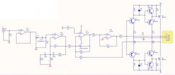
I have made this amp
Output mosfets : IRF9240 and IRF240
+-48v supply
I have problem with no load temp
power dissipation in inductor = 5W and very hot
and power dissipation in all of ohter part=4W
i use 40uh Thyroid inductor
is it normal?
thanks
I have made this amp
Output mosfets : IRF9240 and IRF240
+-48v supply
I have problem with no load temp
power dissipation in inductor = 5W and very hot
and power dissipation in all of ohter part=4W
i use 40uh Thyroid inductor
is it normal?
thanks
Hello Norazmi,
I like to built this 200 watts amp.my first clas D. You have suggested Red T106-2 core for the output. which is not available in my country.
Can I use Yellow core ,if so what changes I will have to make ?
Regards.
Do not use yellow core because it will be hot. you can use the EE25 from former psu DVD and add 3mm gap
sorry my bad English.

hi all
i am doing a ucd version of this amp all credit goes to etjagle the designer. i am combining lory laci input stage, as it has less noise and lorylaci has taken measures of his amp and wave forms are o.k . my board will be big and i am doing single sided..View attachment Class D 200 Wrms with 2 mosfet single sided ucd style schematic.pdf View attachment Class D 200 Wrms with 2 mosfet single sided ucd style board.pdf
i am doing a ucd version of this amp all credit goes to etjagle the designer. i am combining lory laci input stage, as it has less noise and lorylaci has taken measures of his amp and wave forms are o.k . my board will be big and i am doing single sided..View attachment Class D 200 Wrms with 2 mosfet single sided ucd style schematic.pdf
View attachment Class D 200 Wrms with 2 mosfet single sided ucd style board.pdf
Last edited:
the project
Attachments
-
Class D 200 Wrms with 2 mosfet single sided ucd style components full.pdf27.5 KB · Views: 492
-
Class D 200 Wrms with 2 mosfet single sided ucd style pcb bottom.pdf34 KB · Views: 353
-
Class D 200 Wrms with 2 mosfet single sided ucd style schematic.pdf23.6 KB · Views: 414
-
Class D 200 Wrms with 2 mosfet single sided ucd style components .pdf25.7 KB · Views: 296
Thanks to Norazmi.
So I finally built this simple Class D amp,my first.
It had a moderate sized heat sink which got mild warm after an hour of working.
It worked fine with 8ohm loudspeaker .but when driven to a 4 ohm woofer,IRF9640 failed within seconds.
What could be the reasons?
So I finally built this simple Class D amp,my first.
It had a moderate sized heat sink which got mild warm after an hour of working.
It worked fine with 8ohm loudspeaker .but when driven to a 4 ohm woofer,IRF9640 failed within seconds.
What could be the reasons?
Attachments
-
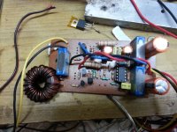 20140604_164428.jpg192.6 KB · Views: 289
i had the same problem and i was very confused because my earlier versions of this amp worked perfectly . but when i used irf 9640 it failed even three hours after working properly. when i changed to irf540n and irf9540n everything is o.k up to now even when using 4ohms at +/-50vlts
this circuit is one of the few reliable circuits i know of pls try harder and i am working on the o.c protection part and also a way of making this amp use hi power like fredos version which uses +/-90vlts and supports 2 ohms . and outputs are only irfp240 and irfp9240 . also is discreet like this amp meaning it does not use ir2xxx driver ic.
hi to all, i made a new pcb board for stereo amplifier.
the pcb is similar to the first tipe posted by norazmi, but i have changed some little things for a better diy realization:
pad is larger and 2k2 resistor is in the original size, heatsink is more simple to assemble, then i have added the inductor on pcb reduced the jumper under the board.
it's only 10x11 cm
View attachment top+bot.pdf View attachment bottom.pdf
good job!
Last edited: