You are using an out of date browser. It may not display this or other websites correctly.
You should upgrade or use an alternative browser.
You should upgrade or use an alternative browser.
Class D 200 Wrms with 2 mosfet cheap
- Thread starter norazmi
- Start date
Hadighorbani
New member
View attachment 5984View attachment 5985another version of 200watts smd amp .thanks to GOD and all diy world .
all the above amps i,ve tested and are working fine
Hi Stewin
this amp need DC,OC and short protection too.
this very cheap amp for everyone and until now only need few bucks to build.im gonna make pcb gerber for it and order it and assembled
hi norazmi welcome back , long time no see
Hadighorbani
New member
hi
what about short circute, OCP and DC protection?
what about short circute, OCP and DC protection?
hi
what about short circute, OCP and DC protection?
use this schematic below by jlester
View attachment Ultra Simple Class D pg56 SClassD Schem.pdf
smd version
hi all , just finished the fully smd version . please check if there are any errors .
also i have added a relay for on delay and dcp also over current protect is on .
where should I add the over temperature ?
if there are any updates ideas or suggestions ,they are highly appreciated ,please post them here . all files are below
core used can be t-106 to t-157
thanking you all in advance steveView attachment gtG 200 watts standard smd ver 2.0 schematic.pdf View attachment gtG 200 watts standard smd ver 2.0 board 1.pdf
 View attachment gtG 200 watts standard smd ver 2.0 board 2.pdfView attachment gtG 200 watts standard smd ver 2.0.zip
hi all , just finished the fully smd version . please check if there are any errors .
also i have added a relay for on delay and dcp also over current protect is on .
where should I add the over temperature ?
if there are any updates ideas or suggestions ,they are highly appreciated ,please post them here . all files are below
core used can be t-106 to t-157
thanking you all in advance steveView attachment gtG 200 watts standard smd ver 2.0 schematic.pdf
View attachment gtG 200 watts standard smd ver 2.0 board 1.pdfView attachment gtG 200 watts standard smd ver 2.0 board 2.pdfView attachment gtG 200 watts standard smd ver 2.0.zipSilvio
Well-known member
Hi Steven, I guess the best way to add the overtemperature protection by inserting a 5V signal to pin 3 of the NE555. obviously this must be sensed from the temperature of the power fet heatsink. You can simply use a bi-metal switch which is normally open and closes when the maximum temperature is reached. Adding another indication to show this condition and also how to isolate the indicators from working together is up to you to figure it out. You can just leave the indicator as it is and lights up with both events when it happens. Simply name it OCP/TEMP
Regards, Silvio.
You can just leave the indicator as it is and lights up with both events when it happens. Simply name it OCP/TEMPRegards, Silvio.
hi silivo ,thanks for the reply . which is better between the 2 circuits .
i wanted to use ntc 10k but the 12volts i wanted to use +/-45vlts from the amps power supply .
do you have or please draw a simplified schematic using 10k ntc and +/-45vlts for supplying the 12v fans power
i wanted to use ntc 10k but the 12volts i wanted to use +/-45vlts from the amps power supply .
do you have or please draw a simplified schematic using 10k ntc and +/-45vlts for supplying the 12v fans power
Attachments
-
 APEX Fan Control PCB.jpg118.2 KB · Views: 29
 -
 APEX Fan Control.jpg73.4 KB · Views: 22
 -
 APEX PWM FAN CONTROL.jpg99.5 KB · Views: 26
Silvio
Well-known member
hi silivo ,thanks for the reply . which is better between the 2 circuits .
i wanted to use ntc 10k but the 12volts i wanted to use +/-45vlts from the amps power supply .
do you have or please draw a simplified schematic using 10k ntc and +/-45vlts for supplying the 12v fans power
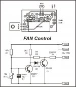
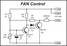
If you intend to supply the 12v from a 45v supply there will surely be a lot of dissipation if you had to use the first circuit with 2 transistor. As you can clearly see the original supply voltage is 15v on the schematic.
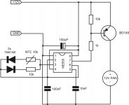
On the other hand the supply voltage of the second circuit is also 12v but I guess the NE555 is controlling the fan speed by pulse width modulation. This type will handle dissipation in the switching transistor more safely although I can see the voltage feeding it is still quite high.
Using a dropper resistor still has to be quite large in wattage as it will get very hot due to the voltage difference is large.
These are your options
1) You either use a small iron core 12v transformer to supply the fan/s
2) You can tread a couple of turns around the main transformer center core of your smps (if you have space) to provide the 12v-15v needed. I do not know the turns ratio of your transformer but they can be easily calculated according to the primary turns. The wire can be ECW or better still CAT5 solid core insulated wire. This you wind on top of everything and there will not be the need to tape it up, just twist the ends together with enough length to arrive to the place needed to feed the fan control circuit.
Regarding the schematics I think they are copied from circuits of amplifiers and they are surely tested and work fine. I am adding a schematic which is a part of my 2KW smps. This was supplied from an auxiliary winding from the main trafo. It was tested with 3 X 80mm fan motors and can take them without any trouble. The darlington transistor was an old stock of mine but you can substitute it with TIP122 or similar.

Regards Silvio
Silvio
Well-known member
Well as you can see from all the schematics that the pass transistor controlling the fan speed need a lot of gain in the base/gate. I guess you can use a fet instead but I am not sure how it would behave. You see a fet needs more voltage in the gate to start saturation. You can use a small transistor like 2N2222 or any small NPN transistor and hook up the TIP41 in the darlington fashion. This will boost the gain at the base of the power transistor. You can build the circuit on a breadboard and try it out. It could be that you may need to change the value of some of the resistors to get the circuit working to your need. Be careful to monitor the temperature range and at what temperature the fan gets the maximum voltage (12v). I guess this should be around 45-50 degrees.
Regards, Silvio
Regards, Silvio
Well as you can see from all the schematics that the pass transistor controlling the fan speed need a lot of gain in the base/gate. I guess you can use a fet instead but I am not sure how it would behave. You see a fet needs more voltage in the gate to start saturation. You can use a small transistor like 2N2222 or any small NPN transistor and hook up the TIP41 in the darlington fashion. This will boost the gain at the base of the power transistor. You can build the circuit on a breadboard and try it out. It could be that you may need to change the value of some of the resistors to get the circuit working to your need. Be careful to monitor the temperature range and at what temperature the fan gets the maximum voltage (12v). I guess this should be around 45-50 degrees.
Regards, Silvio
hi silvio . meaning that the fan runs slow but at hotter temperatures the fan runs very fast?
my new high efficiency class d amp using tl494 is ONLINE!!! https://www.facebook.com/harisd9401/videos/950334128753237/
hi all . below is the original schematic of this project i managed to translate it . have fun all :
 View attachment switchingamp_189.pdf
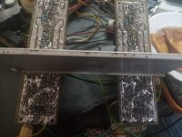
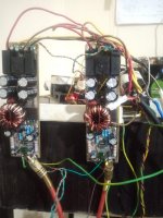
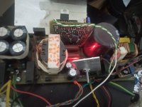
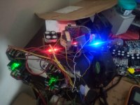
: View attachment switchingamp_189.pdfhi all , i have made many pcb versions of this amp ,
i still stick to the original schematic in the above link.
the thing i found interesting in this amp is that it requires original tl074/084 and bc327 and bc337 . if you compromise in this area it will consume alot of current at idle an produce hf noise.
my question is ,can i use two lm339 instead of tl074/084 and which other transistor can i use to substitute bc337 and bc327 ?
vvv vvv my current project vvv vvv
Attachments
-
200wt strd ver1.2 dc prtc long schematic .pdf.pdf37.1 KB · Views: 4
-
200wt strd ver1.2 dc prtc long pcb top .pdf.pdf29.6 KB · Views: 3
-
200wt strd ver1.2 dc prtc long pcb bottom.pdf38.7 KB · Views: 3
-
GerberFiles 200wt strd ver1.2 dc prtc long gerber.zip187.2 KB · Views: 4
-
200wt strd ver1.2 dc prtc long bom.pdf120.9 KB · Views: 3
-
 IMG_20210322_103048_038.jpg701.5 KB · Views: 5
 -
 IMG_20210322_102949_683.jpg775.4 KB · Views: 6
 -
 IMG_20210322_194929_550.jpg717.6 KB · Views: 5
 -
 IMG_20210322_194954_962.jpg512.1 KB · Views: 5
 -
 IMG_20210322_195027_990.jpg652.2 KB · Views: 5
Silvio
Well-known member
A TLO74 is a Jfet input opamp designed for audio purpose. Its input bias current is 65pA. it is very low noise and has good noise rejection.
An LM339 is a voltage comparator and is more suited for voltage comparison purpose such as protection circuitry etc. input bias current is 25nA.
2 x NE5532 will also make you a quad opamp and this will be a better choice than LM339 for your particular case. You have to alter the pcb for this.
Alternative transistors for BC327 are 2N4403, BC488, BC638, 2N4402, 2N3702, 2N3703, BC486, Bc490 and BC328 (The pinout configuration of the alternative or substitute transistors shown here many be different from the BC327
For Bc337 you can use 2n2222 instead.
Basically any small transistor suited for audio purpose with a collector emitter voltage of 40v will be suitable.
Another choice I am thinking of is 2n5551 and 2n5401 although the voltage is over rated at 150 volts I guess will still do the job fine.
Good luck regards Silvio