Hi all,
I am new here. First, please scuze me if my english is not perfect, it's not my primary language")
Second, MicrosiM I want to congrulate you about your work and your experiments. I laugh a lot when you often tell that you talk about thing you really tested comparing to other which claims a lot but without show anything
It makes me laugh because I am facing the same on some experiments I worked on in the past
If I post here it's because a friend asked me if I can develop for him a 3kW DC/DC converter. Input voltage 48V DC ( 42V min 55V max), and output adjustable from 220 to 240V DC.
It's to use in its hybrid car, to extend the range in pure electric mode with a supplementary battery pack.
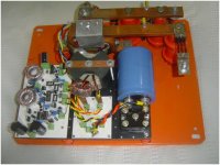
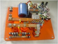
He first used a kit from Enginer, and had a lot of problem with the converter and even with the battery pack. Now Enginer refuse to change another time it's broken converter under warranty !! It's why he asked to me to try to repair it, it's what I done (but for how many time !?), but also to look if I can build a new one, more reliable.
Because I like discover new area of electronic, I am looking for the maximum of information on SMPS before try to do anything. It's why I found this site and this forum !
I quickly understood the basic theory of this kind of DC-DC converter, but I know it's really complex in practice when we reach these output power !
My first idea to build this converter was to parallelize multiple small converter based on smaller transformer instead to use only one big transformer. Also, my idea was to parallelize the transformers's primary, but put in serie the transformer's output.
After my friend gave my the broken converter from Enginer and open it, I see they use exactly the same technic. Thus I think the basic idea is good, but the enginer realization is not reliable.
So what I want to do is to use a push pull technology with 6 transformers and 12 associated mosfets. If I put the 6 output transformer in serie just before the ultrafast rectifier bridge, the transformer can be 1:1, because with 42V at the input I will have 42x6 = 252V at the output (with max duty cycle)
Do you think this configuration can be a good idea ?
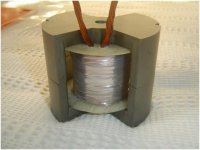
Next, I need to learn about transformers, because I think about winding them myself on standard core ETDxx.
If I use 6 transformer (1:1), one transformer needs to manage 3000/6 = 500W. From your experience, what is the best transformer ETD size for this power ? ETD44 ? From the current side, if I take the most unfavorable configuration (input at 42Vdc), each transformer need to manage 12A.
With the 6 transformers solution, the advantage is that I can first work on a "small" 48Vdc/48Vdc 500W converter based on a single transformer, to optimize the transformer winding, the electronic and the regulation, and after this step I can realize the big converter with 6 transformers with the ouputs in serie.
Thank again for this site and this forum !
Regards,
Cyril
I am new here. First, please scuze me if my english is not perfect, it's not my primary language
Second, MicrosiM I want to congrulate you about your work and your experiments. I laugh a lot when you often tell that you talk about thing you really tested comparing to other which claims a lot but without show anything
It makes me laugh because I am facing the same on some experiments I worked on in the past
If I post here it's because a friend asked me if I can develop for him a 3kW DC/DC converter. Input voltage 48V DC ( 42V min 55V max), and output adjustable from 220 to 240V DC.
It's to use in its hybrid car, to extend the range in pure electric mode with a supplementary battery pack.
He first used a kit from Enginer, and had a lot of problem with the converter and even with the battery pack. Now Enginer refuse to change another time it's broken converter under warranty !! It's why he asked to me to try to repair it, it's what I done (but for how many time !?), but also to look if I can build a new one, more reliable.
Because I like discover new area of electronic, I am looking for the maximum of information on SMPS before try to do anything. It's why I found this site and this forum !
I quickly understood the basic theory of this kind of DC-DC converter, but I know it's really complex in practice when we reach these output power !
My first idea to build this converter was to parallelize multiple small converter based on smaller transformer instead to use only one big transformer. Also, my idea was to parallelize the transformers's primary, but put in serie the transformer's output.
After my friend gave my the broken converter from Enginer and open it, I see they use exactly the same technic. Thus I think the basic idea is good, but the enginer realization is not reliable.
So what I want to do is to use a push pull technology with 6 transformers and 12 associated mosfets. If I put the 6 output transformer in serie just before the ultrafast rectifier bridge, the transformer can be 1:1, because with 42V at the input I will have 42x6 = 252V at the output (with max duty cycle)
Do you think this configuration can be a good idea ?
Next, I need to learn about transformers, because I think about winding them myself on standard core ETDxx.
If I use 6 transformer (1:1), one transformer needs to manage 3000/6 = 500W. From your experience, what is the best transformer ETD size for this power ? ETD44 ? From the current side, if I take the most unfavorable configuration (input at 42Vdc), each transformer need to manage 12A.
With the 6 transformers solution, the advantage is that I can first work on a "small" 48Vdc/48Vdc 500W converter based on a single transformer, to optimize the transformer winding, the electronic and the regulation, and after this step I can realize the big converter with 6 transformers with the ouputs in serie.
Thank again for this site and this forum !
Regards,
Cyril