Drive signal issues with half bridge

212Vac measurements

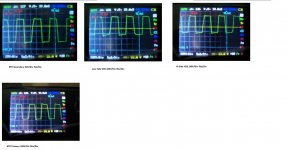
Hi really sorry for these measurements but this is the only waveforms i can get before my X100 probe gets here 212Vac Measurements.jpg. The rise and fall times aren't time accurate but the top and botom of the wave are. This was taken with SMPS isolated and fed with 212Vac and 200W bulbs in series and 100W bulbs on each output no core heating no mosfet heating
 
Hi Microsim thanks for the reply. The next test is to connect it straight to 230Vac and see how it performs. I will do it today and post back. Sorry a bit off topic but i would be grateful i could you please answer these two questions:
1) Is 800W at 70Khz achievable with an ETD44?
2) Which IGBT have you had most success with for less than 1KW output power hard switching.

Thanks.
 
Last edited:

MicrosiM

Administrator
Staff member
IGBTs

Hi Microsim thanks for the reply. The next test is to connect it straight to 230Vac and see how it performs. I will do it today and post back. Sorry a bit off topic but i would be grateful i could you please answer these two questions:
1) Is 800W at 70Khz achievable with an ETD44?
Yes 800W is very easy with ETD44

2) Which IGBT have you had most success with for less than 1KW output power hard switching.
You can use, HGTG30N60A4D


Thanks.

Please see answers above, and there are other IGBTs from IRF, will try to show more numbers
 
Great News!!!!!

Microsim thanks for the answers i got two ETD44 that i need to pick up at post and planning a a half bridge with each of them.
I have very good news!!!!!!!!! The smps survived direct 230Vac test no core heating no mosfet heating! I loaded it with 2x100W bulbs i got +-32V on output. Loaded with 4X100W bulb and same voltage. While connecting the bulbs i accidentally connected 3 bulbs to one line and 1 bulb to another line and it even survived that giving 31.2V on one side and 35V on the other.I only realized that when i saw the voltage and checked the circuit.
I owe you a lot! Thanks for all your help and patience in helping this to get working. I will make a pcb for the current SMPS before i connect it to an amplifier. I will post the pcb here after i complet the layout. I will use same layout as i did on the proto board and a card for the oscillator
 

MicrosiM

Administrator
Staff member
Microsim thanks for the answers i got two ETD44 that i need to pick up at post and planning a a half bridge with each of them.
I have very good news!!!!!!!!! The smps survived direct 230Vac test no core heating no mosfet heating! I loaded it with 2x100W bulbs i got +-32V on output. Loaded with 4X100W bulb and same voltage. While connecting the bulbs i accidentally connected 3 bulbs to one line and 1 bulb to another line and it even survived that giving 31.2V on one side and 35V on the other.I only realized that when i saw the voltage and checked the circuit.
I owe you a lot! Thanks for all your help and patience in helping this to get working. I will make a pcb for the current SMPS before i connect it to an amplifier. I will post the pcb here after i complet the layout. I will use same layout as i did on the proto board and a card for the oscillator

Zeus,

No need to thank me, I am trying to help every one, Thanks for being here showing your work and progress of SMPS.

I know the taste of success, specially when you reach it.

diysmps gives real information's and real help, not like diyaudio, all they give you is words @ sky.

I am really glad for your results. but still dont know what was wrong with your SMPS, please show your final schematic, and let me know changes.

Try to load your SMPS 500W. it wont blow, just do it ;)
 
Yay!!!

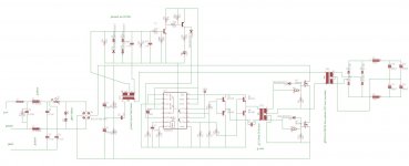
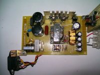
Hi Microsim here is the latest schematicfinal schematic.JPG and circuit layout Circuit%20Layout.jpg. What did make the SMPS work was the change in layout by moving the oscillator far outside on a card, bringin the core closer to the Mosfets and properly laying out the connections i had some wires crossing below the board. They were insulated but most probably causing the mosfets to cross conduct by inducing false turn on. there is also one other thing that i changed, i made the connections with those output wires coming from pc smps they behave very strangely when used tinned with solder and connected to high frequency ac signals they seem to be good for dc only.
I made the new connections using basic copper wire and it worked great.

One other thing is that all the cores used here are recycled from PC PSU i.e. main core and current sense tranfo. The GDT core came from a CFL lamps a 100W philips white light model i think. If i did not purchase and inductance meter i would have never been able to find out the AL of these core and use the proper one.

The core AL are as follows: Main core 3885 GDT is around 6000 or 9000 i think i mentionned it somewhere in this post.

Bad news i don't have a 500W load handy i need to build or assemble one. Do you have any suggestion? 10W resistors on heatsink?+fan or metal resistors on heatsink+fan? Or is there any other way? I read about oil cooled resistors but it seems annoying and dangerous


Diyaudio is becoming more and more worse as days go by. I don't understand how some people there tell me that things are incorrect in my design and I never saw them post any projects and they give you book citations and formulae. Many times i have seen some people telling me what i did in my amp design/setup was bad and when you look at their project they did worse and everybody applause and copy their designs. If it weren't to do things by myself i would never been able to achieve this: http://www.diysmps.com/forums/showt...red-loudspeaker-inspired-from-studio-monitors and am glad i did it without their help
 
Last edited:

MicrosiM

Administrator
Staff member
Hi Microsim here is the latest schematicView attachment 1318 and circuit layout View attachment 1317. What did make the SMPS work was the change in layout by moving the oscillator far outside on a card, bringin the core closer to the Mosfets and properly laying out the connections i had some wires crossing below the board. They were insulated but most probably causing the mosfets to cross conduct by inducing false turn on. there is also one other thing that i changed, i made the connections with those output wires coming from pc smps they behave very strangely when used tinned with solder and connected to high frequency ac signals they seem to be good for dc only.
I made the new connections using basic copper wire and it worked great.

One other thing is that all the cores used here are recycled from PC PSU i.e. main core and current sense tranfo. The GDT core came from a CFL lamps a 100W philips white light model i think. If i did not purchase and inductance meter i would have never been able to find out the AL of these core and use the proper one.

The core AL are as follows: Main core 3885 GDT is around 6000 or 9000 i think i mentionned it somewhere in this post.

Bad news i don't have a 500W load handy i need to build or assemble one. Do you have any suggestion? 10W resistors on heatsink?+fan or metal resistors on heatsink+fan? Or is there any other way? I read about oil cooled resistors but it seems annoying and dangerous


Diyaudio is becoming more and more worse as days go by. I don't understand how some people there tell me that things are incorrect in my design and I never saw them post any projects and they give you book citations and formulae. Many times i have seen some people telling me what i did in my amp design/setup was bad and when you look at their project they did worse and everybody applause and copy their designs. If it weren't to do things by myself i would never been able to achieve this: http://www.diysmps.com/forums/showt...red-loudspeaker-inspired-from-studio-monitors and am glad i did it without their help

Zeus,

I am glad for your success, and the experience you have by now, And i would like to thank you again for sharing some of your projects and ideas.

I think your layout had many problems as I told you in the beginning, but now its OK :)

You should make a PCB, I will give you some guide lines if you would like to.

diyaudio is just a commercial site for making money, and they dont care about any one any more.

many, or all there gives no help, they all want to be above every one. but now you have proven the opposite for them!

NOW!

For your load, you can use HEATER ELEMENTS, same ones I use. try to locate some used ones.

I will appreciate, after you finalize your SMPS, to submit a PDF file containing construction of your SMPS, becuase you have used OLD cores from PC power supplies, as this is a very important thing for many friends here at forums, who dont have access to ETD cores. by that you will help them a lot :UP:

Thank you again ;)
 
Hi Microsim thanks a lot for the reply. I don't mind putting all details here. Would you mind telling me the heater element you are using is destined for which appartus? i think they sell those kettle 1000W heater element here or those 220Vac oven element. 1000-700W forced convection heaters are also on sale here but i don't know if the heating elements can be used.

I will start pcb design today any advice before i start are welcome thanks
 

MicrosiM

Administrator
Staff member
Hi Microsim thanks a lot for the reply. I don't mind putting all details here. Would you mind telling me the heater element you are using is destined for which appartus? i think they sell those kettle 1000W heater element here or those 220Vac oven element. 1000-700W forced convection heaters are also on sale here but i don't know if the heating elements can be used.

I will start pcb design today any advice before i start are welcome thanks

kindly watch video here, and see my heater elements
 
Hi Microsim, i have seen your load test videos and the type of wirewound heater elements you are using. I have tried to ask for this kind of heater element here its not available. Standard kettle elements are available or electrical immersion heater used to back up solar water heater are available apparently reated a few hundred watts to several thousand watts. I will try to see what i can get around here. In the meantime am converting my schematic in target pcb and creating the cores as these packages are missing. Once done i will post the pcb for the controller card and the power pcb.
 

MicrosiM

Administrator
Staff member
Hi Microsim, i have seen your load test videos and the type of wirewound heater elements you are using. I have tried to ask for this kind of heater element here its not available. Standard kettle elements are available or electrical immersion heater used to back up solar water heater are available apparently reated a few hundred watts to several thousand watts. I will try to see what i can get around here. In the meantime am converting my schematic in target pcb and creating the cores as these packages are missing. Once done i will post the pcb for the controller card and the power pcb.

Those used for Kettel can do the Job also, get some of 100s of Watts

and make them your load :)
 
hi Microsim thanks for the reply. Searching for heater elements was not conclusive in the stores i went to except i found a complete chinese made kettle for less than $10. I have checked ebay and they sell 1000-2000W immmersion heater elements for $15-30. I will keep checking and make up my mind. In the meantime pcb layout is going good and my ETD44 cores are here :)! I will need to plan on how the next smps for them asnd post the complete pcb as its done.
 
Another very good test result it survived pushing an amp connected to an 8 ohm load and biased far end class AB if not class A. the mosfets got very hot at his point and i backed it up with a fan.the other only thing that got warm were the diodes(not boiling like the mosfets) thats normal i think. Even mometarily increased the load to 4 ohm at heavy bias and it kept working without blowing.Backed down the bias to class AB where the amp was supposed to work and the mosfets were as cold as stone :)
 

MicrosiM

Administrator
Staff member
That sounds great!


every thing can be tweaked to the best, we can do modifications if we need

Good luck
 
Hi Microsim, thanks for the reply. I listened to music at reasonable level with the smps powering my amp for one hour without getting any issue connected to a 2 way 3 speaker with passive x-over in an open baffle enclosure it did sound pretty good even the highs were most mashed up like with some ordinary EI transfo and am using a crappy 4 ohm piezzo tweeter in it. Output voltage after 1 hour music playing:+34.8V -34.5V mosfet dead cold, core barely warm and same for diodes. However the output transistor on my test amp got quite hot at this voltage level (~100W 4Ohm) normal for a class AB amp.

Well about tuning i don't mind, i will post the schematics here today i did in target 3001. I was thinking of doing the following:
1) Increase input capacitance from 2X470uF to 4X470uF
2) Parallel each BY396 ouput diode with another for greater current handling
3) Increase output capacitance from 4X470uF to 8X470uF
4) Add an over temperature protection for the mosfet on the oscillator card. I have it in schematic i need to test it


If you have any ideas or need any info to help tuning don't hesitate.
 

MicrosiM

Administrator
Staff member
1) Increase input capacitance from 2X470uF to 4X470uF

This is good

2) Parallel each BY396 ouput diode with another for greater current handling

This is not needed if you are using robust diodes like MUR810, but it can be done, it wont hurt.

3) Increase output capacitance from 4X470uF to 8X470uF

I dont think this is necessary. you can see results by yourself, QSC uses 6x470uf in 2x1000W amplifier!

4) Add an over temperature protection for the mosfet on the oscillator card. I have it in schematic i need to test it

This is needed


:D
 
just an update on the over temperature the link i shown above doesn't fit my linking instead i developped a vbe multiplier using TIP41C connected to a CCS. I just need to send the output to an comparator a 741 should do the job to switch off the oscillator as temeprature reaches 100C. Its instanteneous compared to the ESP circuit which takes some seconds to trigger and produces <1V at 100C and 6.32V at room temperature
 

MicrosiM

Administrator
Staff member
just an update on the over temperature the link i shown above doesn't fit my linking instead i developped a vbe multiplier using TIP41C connected to a CCS. I just need to send the output to an comparator a 741 should do the job to switch off the oscillator as temeprature reaches 100C. Its instanteneous compared to the ESP circuit which takes some seconds to trigger and produces <1V at 100C and 6.32V at room temperature

That circuit is very good.
 
Top