Easy SMPS for everyone :)

rocifier

New member
Cool I'm going to try building this as my first SMPS. What are the limitations I should know about when compared to a more complex one, eg. with opto-isolated feedback, PWM, etc. ?
 

rocifier

New member
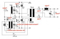
k so I've been planning this out some and I'm keen to make the half-bridge FET version, but I'm unsure of a lot of the components. I've labelled what I'm not sure about below:

questions.jpg

Also, is it easy to make this power supply output a positive and negative voltage, or can it only do positive in relation to a reference?
 

rocifier

New member
Ok, I ripped apart a fairly hefty transformer from a TV I found on the side of the road to get down to the core. I don't know if it's E33 or whatever. Can I use this?

ripped transformer.jpg
 

blasphemy000

New member
Looks like you had a rough time stripping down that transformer. If you peal the strip of yellow tape off the outside of the square part, this usually requires a sharp knife, then place the transformer into boiling water for a few minutes, the glue/epoxy that holds the two halves of the ferrite together will soften and you can usually take it apart. The boiling time can range anywhere from a minute to 15 minutes, depending on how long it takes for the hot water to penetrate into the center leg of the core and soften the glue in there. I've had a few that just refused to come apart. Also, with tiny transformers, the heat can soften the binding agent that makes up the ferrite core and the legs can become semi-flexible and will sometimes break easier. Still, I've had good luck with this method overall.
 

rocifier

New member
Ahhh okay that's good to know for next time thanks. It wasn't quite as bad as it looks, it kept shedding apart like an onion on both sides. I decided I'm going to design an active PFC supply and post it on here instead of building this one, since I have a certain application in mind. Keep an eye out for it.
 

rocifier

New member
Can someone give an overview of how this circuit works? I'm trying to understand it more, but I'm not sure where to start.
 

alertlink

New member
The first pulse is generated due to firing of DIAC, causing the FET to conduct and then push-pull oscillator starts to operate.
 

rocifier

New member
Hey I'm trying to wind L1/L2 on a different toroid core. What inductance value is it? Also, what's the advantage of being common-mode here?
 

rocifier

New member
Does anyone know if Acca is still alive? I haven't seen him reply to any questions. In regards to efficiencies I can't comment too much because I haven't completed my build yet. But because it's self-oscillating the core needs to saturate to drop and then reverse the voltage to switch the other other transistor. So there is some time which is spends saturated, which is not very efficient. But overall that time is small, so it shouldn't be too bad I hope... in fact looking back at the waveforms Acca posted, that time is negligible. I guess the main inefficiency would come from the voltage being out of phase with the current, but I'm still learning and have no idea how this situation can physically happen (it always seems to, hence the desire for power factor correction). Please correct me if I'm wrong.
 
Last edited:

rocifier

New member
It's dead, Jim!

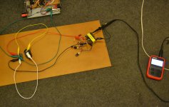
Hmm, so I got my build hacked together and I'm just trying to get something reading off the main transformer. So far just 0V over primary, secondary, feedback. I tried switching polarity of feedback but no difference. Now I see the importance of CATIII scope since the battery one I'm borrowing can only go up to 100V (such a lame design). Any ideas how I can debug this problem? I do have a good multimeter than can read AC and DC over 400V. Photo of setup ready to explode on a fireproof board, but it's dead Jim:
DSC_0001.JPG

By the way I replaced a 0.1uF cap with a 1uF cap because I didn't have the right one. Does that matter?
 

13005

New member
سلام نیازی به بستن مدار نیست
این مدار دقیقا شبیه مدار بالاست الکترونیکی میباشد فقط باید ۴تا دیود بهش اضافه کرد
 

fan34574

New member
Ok, I ripped apart a fairly hefty transformer from a TV I found on the side of the road to get down to the core. I don't know if it's E33 or whatever. Can I use this?

View attachment 5061

how did your attempts at using this core go? i am planning on building two of them (smps) and so far i do have all parts except that i only have one ee19, however i do have a couple of hefty transformers from a crt tv laying around so maybe i can put them to good use if using them was successfull.
 

expressel

New member
Why not two feedback turns instead an another transformer? wiz:;
It can be also with two optocouplers or with an optocoupler+transformer combo.
I love optocouplers, Is they slow for this ?
 
Last edited:

Abet

New member
hi acca pls tell me the number of turns of gdt transformer where it is written 12.... 15v . i want to use e55 core with four irfp 460

Hi Stewin,
Do you still have the details of the gdt of the fet version?..I keep seeing details for the bdt (bjt version) and so far only one for gdt and that is from member Panos posting (still needing confirmation at the time of this posting).

I build it but since I cannot find the exact details for the gdt, I just followed as per the schematic, I used a green torus..but no success. It is a guessing game for me so far being 4 years coming late for this build.

Regards,
Albert
 
Top