Sandy
New member
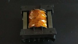
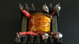
Ok, just about to start my first coil job ") I have seen various ways of winding the coils on these cores, and looking for some hints why one way or the other. The Core is a TDK ETD-29 core with matching coil form.
I have seen various ways of winding the coils on these cores, and looking for some hints why one way or the other. The Core is a TDK ETD-29 core with matching coil form.
The coil is for a 50kHz-60kHz dc to dc inverter (push pull topology) with 4 turns for each of the primary and 160 Turns of on the secondary.
Primary wire bundle is a twist of 6x22awg wires
Secondary wire is a single 28awg wire.
For this I think I'm winding the primary bifilar, and I think it will just fit across one layer on the coil form.
So the question is... Primary first, then secondary, or the reverse. And of course why so I might learn something at the same time.
Thanks for any tips!
Sandy
I have seen various ways of winding the coils on these cores, and looking for some hints why one way or the other. The Core is a TDK ETD-29 core with matching coil form.The coil is for a 50kHz-60kHz dc to dc inverter (push pull topology) with 4 turns for each of the primary and 160 Turns of on the secondary.
Primary wire bundle is a twist of 6x22awg wires
Secondary wire is a single 28awg wire.
For this I think I'm winding the primary bifilar, and I think it will just fit across one layer on the coil form.
So the question is... Primary first, then secondary, or the reverse. And of course why so I might learn something at the same time.
Thanks for any tips!
Sandy