DjLeco
Moderator
After studying and studying, Yamaha and Labgruppen TD amplifiers schematics, I decided to give a try to implementate something on mine AB class amplifier.
So I go to the Yamaha's Eee schematics (autooscilant) and extracted what I need for implementation to see if it works.
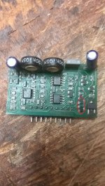
Yamaha uses on each rail +Vcc and -Vcc ,3 pairs of transistors in voltage amplifier (2SA1492A +2SC3856A) ,I used just one pair of MJL21195+MJL21196 , and 3 pairs of mosfets in current amplifier (2SK3004), I used one pair of IXTQ52N30P (very fast and small gate charge mosfet)in tests.
Officially Yamaha's use +/- 155Vcc in idle and in load, the supply falls down till around +/- 110Vdc, they use a very small power supply SMPS, but that's not important.
After tests and tests , starting from +/- 110Vdc, I pushed far to +/- 170Vcc in idle(+/- 165Vcc in full load), because mine SMPS is with PFC, and drops just 10 Volts (+5 -5 on each rail) from idle to full load, and I have obtained what U can see in the movies.
Don't laugh about "spider" connection of SMPS and TD part, just take couple minutes of your life and watch the small movies on youtube.
Comments are very appreciated and welcomed, expecially about output power!
Next week I will give a try, to implement modulate TD like Labgruppen, at 250Khz and 500Khz too, because on autooscilant Yahana TD Design, I hear sounds in colis, and gives small switching artefacts, more visible at 1000Hz.
I obtained 109-110Vrms on 4 ohm dummy load, and trying into clip, smps has shut down (I have calibrate protection to act at around 3400-3500W)
[video=youtube;7bMcDikRjTg]http://www.youtube.com/watch?v=7bMcDikRjTg&feature=player_embedded[/video]
[video=youtube;guoLw9e4Seg]http://www.youtube.com/watch?v=guoLw9e4Seg&feature=player_embedded[/video]


So I go to the Yamaha's Eee schematics (autooscilant) and extracted what I need for implementation to see if it works.
Yamaha uses on each rail +Vcc and -Vcc ,3 pairs of transistors in voltage amplifier (2SA1492A +2SC3856A) ,I used just one pair of MJL21195+MJL21196 , and 3 pairs of mosfets in current amplifier (2SK3004), I used one pair of IXTQ52N30P (very fast and small gate charge mosfet)in tests.
Officially Yamaha's use +/- 155Vcc in idle and in load, the supply falls down till around +/- 110Vdc, they use a very small power supply SMPS, but that's not important.
After tests and tests , starting from +/- 110Vdc, I pushed far to +/- 170Vcc in idle(+/- 165Vcc in full load), because mine SMPS is with PFC, and drops just 10 Volts (+5 -5 on each rail) from idle to full load, and I have obtained what U can see in the movies.
Don't laugh about "spider" connection of SMPS and TD part, just take couple minutes of your life and watch the small movies on youtube.
Comments are very appreciated and welcomed, expecially about output power!
Next week I will give a try, to implement modulate TD like Labgruppen, at 250Khz and 500Khz too, because on autooscilant Yahana TD Design, I hear sounds in colis, and gives small switching artefacts, more visible at 1000Hz.
I obtained 109-110Vrms on 4 ohm dummy load, and trying into clip, smps has shut down (I have calibrate protection to act at around 3400-3500W)
[video=youtube;7bMcDikRjTg]http://www.youtube.com/watch?v=7bMcDikRjTg&feature=player_embedded[/video]
[video=youtube;guoLw9e4Seg]http://www.youtube.com/watch?v=guoLw9e4Seg&feature=player_embedded[/video]