Flyback SMPS transformer calculations

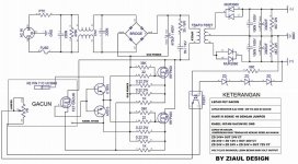
I have built this power supply but I can't figure out the correct number of turns for the transformer. here is the PDF schematic:

View attachment Fly-Back 13.8v 10A.pdf
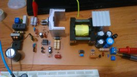
Comp.JPG
This SMPS is based on UC3842 controller and is supposed to work with 220V and the output voltage is 13.8 Volts at 8 Amps.
This is my first Flyback and it is actually a clone of this Industrial SMPS you can see here:
http://danyk.cz/reverz44_en.html

Before this I had made several Half bridge SMPS based on IR2153 using the ExcellentIT ver. 7100 calculator easily. But this one seems like a nightmare.
I tried an approximate winding of "40 turns for Primary" , "20 turns for Secondary" and "20 turns for auxiliary" and it worked when the input voltage was 95 volts.
With 220 volts, transformer started clicking really badly and also the output voltage was too low and not stable.

It is really frustrating I really can't figure out the winding turns. Would you guys please help with the transformer design?
Here are some details about the circuit:
Core : EDT-39 (effective area = 12.5cm square / effective lenght = 92.2 mm)
Transistor: 2SK2645 (600V 9A RDSon = 1.2 ohm)
Output Diode : MBR20100 ( 100v , 20A , VF=.95 volt)
Input voltage: 220 volt
Output: 13.8 Volts 8 Amps
Thank you
Any help is highly appreciated
 

Silvio

Well-known member
I have built this power supply but I can't figure out the correct number of turns for the transformer. here is the PDF schematic:

View attachment 6649
View attachment 6648
This SMPS is based on UC3842 controller and is supposed to work with 220V and the output voltage is 13.8 Volts at 8 Amps.
This is my first Flyback and it is actually a clone of this Industrial SMPS you can see here:
http://danyk.cz/reverz44_en.html

Before this I had made several Half bridge SMPS based on IR2153 using the ExcellentIT ver. 7100 calculator easily. But this one seems like a nightmare.
I tried an approximate winding of "40 turns for Primary" , "20 turns for Secondary" and "20 turns for auxiliary" and it worked when the input voltage was 95 volts.
With 220 volts, transformer started clicking really badly and also the output voltage was too low and not stable.

It is really frustrating I really can't figure out the winding turns. Would you guys please help with the transformer design?
Here are some details about the circuit:
Core : EDT-39 (effective area = 12.5cm square / effective lenght = 92.2 mm)
Transistor: 2SK2645 (600V 9A RDSon = 1.2 ohm)
Output Diode : MBR20100 ( 100v , 20A , VF=.95 volt)
Input voltage: 220 volt
Output: 13.8 Volts 8 Amps
Thank you
Any help is highly appreciated

Here is some software so that you can calculate your number of turns for the flyback

PS if you really wanted to clone the smps then you should have dismantled the transformer and counted the number of turns. There also may be a gap in the center leg of the core.

Regards Silvio
 

Attachments

  • Flyback(6000).zip
    483.2 KB · Views: 189
Last edited:
Thank you Silvio for your attention. I actually cloned an existing reversed engineered schematic. So I didn't have my hands on the transformer.
I wound a core using this software but I didn't like the result. Core saturates in no time and output starts oscillating when connected to 220 volts.
Since the output diode is unknown in the original schematic, I have to use something different and do all the calculations according to the diode of my choice.
I've wound the core 4 times with no perfect result. Error margin for transformer design is very narrow in this topology and transformer needs to be perfectly calculated and constructed.
Regards
Ciro

Best regards
Ciro
 

Upik

Member
Thank you Silvio for your attention. I actually cloned an existing reversed engineered schematic. So I didn't have my hands on the transformer.
I wound a core using this software but I didn't like the result. Core saturates in no time and output starts oscillating when connected to 220 volts.
Since the output diode is unknown in the original schematic, I have to use something different and do all the calculations according to the diode of my choice.
I've wound the core 4 times with no perfect result. Error margin for transformer design is very narrow in this topology and transformer needs to be perfectly calculated and constructed.
Regards
Ciro

Best regards
Ciro


Maybe you can try it with 500uh ,, and on the core that has air gap.
 

Silvio

Well-known member
Thank you Silvio for your attention. I actually cloned an existing reversed engineered schematic. So I didn't have my hands on the transformer.
I wound a core using this software but I didn't like the result. Core saturates in no time and output starts oscillating when connected to 220 volts.
Since the output diode is unknown in the original schematic, I have to use something different and do all the calculations according to the diode of my choice.
I've wound the core 4 times with no perfect result. Error margin for transformer design is very narrow in this topology and transformer needs to be perfectly calculated and constructed.
Regards
Ciro

Best regards
Ciro

Hi well I gave you the software as the one you mentioned was for half/full bridge and push pull. The software I sent is for flyback.

Well regarding your results it is clear that the primary inductance at the higher voltage is not enough hence the core saturation. Be also care full regarding the core material and also the gap in the center leg. The larger the gap the lower the inductance you will have for the same number of turns. Check and compare the switching frequency and see that this is the same as the original.

good luck Silvio
 

Silvio

Well-known member
Lately I re-wound a small transformer for an auxiliary supply (EE22 with no gap) running at around 120Khz. The primary inductance was a bit more than 4mH. This is to give you an idea of what you need for operation on 220v. If the core is bigger then it need less turns to get to the same inductance because of the larger core area. However if you make a gap in the center leg than you will need more turns as the permeability of the core gets less with the gap for the same inductance. In flyback topology the gap is needed for larger current as this will help the core to go for larger flux density without going into saturation.

I hope that helps

Silvio
 

Silvio

Well-known member
Diode gone wild did a good job for you well you can get a ready made one for $8 from E-bay
 
Thank you Silvio for your help. I will definitely try some more core winding and tests. Constructing such a SMPS should not be a big deal and I'm curious to learn about Flyback. So i'll make it work and show the results here in this topic as soon as I kill it.
Yes of course I can buy the ready made unit but having the knowledge, I can later integrate this simple yet efficient design in my projects.

Ciao!
 
I was suspicious about the 16V VCC that is needed for UC3842. Obviously there must not exist the proper VCC if the voltage at output is oscillating around 8-10 volts.
So I decided to power up the chip from a linear power supply instead of using the auxiliary winding. But seems It doesn't work in this way because absolutely no voltage appears in secondary winding!
There is no output at Pin 6 so it wont drive the gate of the MOSFET!!
It makes no sense to me!! Do you have any idea why it powers up ONLY when it is connected to auxiliary winding?
 

Silvio

Well-known member
Here are a few hints to help you solve the problem

Add a few turns to the trafo without dismantling it and put the winding in series with the auxiliary winding thus adding turns will add more voltage to the IC and see how it goes.

On the other hand I am thinking of that it could be possible the the chip is shutting down for some reason. Giving direct voltage from an external supply should bring the chip running normally. (I hope you grounded the negative of the external power supply to the pcb ground)

Thinking of what you said in the beginning of this tread. You said that the supply works at around 90v or so but as you raise the voltage strange things start happening. Well then why at 90v there was enough voltage to keep the chip running? There is also another thing that might not be right such as the winding of the auxiliary being connected in the wrong phase.

I am just trying to help you the best I could
 

Upik

Member
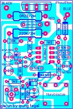
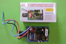
Hi mr.silvio ,, this is a universal pwm that is sold in the market in my country ,,, and is booming among lovers of audio.mereka build it for cheap smp ... but i always fail to build it ... they can not afford up to 1000watt even ... yes if you want to give a lesson about this topology, it sounds very good. is uc3842 is same as uc3843


And here's an example of a standard pwm and scheme among beginners
downloadfile.jpg FB_IMG_1526400726852.jpgFB_IMG_1522899393448.jpg
 
Last edited:

Silvio

Well-known member
Hi Upik, All I can see is here is a way to utilize the driver and enhancing more current in the main transformer for higher current. This is achieved by adding more transistors in parallel with the output of the main pcb.
The topology is flyback and here you only use the first quadrant of the transformer flux. This means that for a given core size you will only get say 1/2 the power compared to a half bridge.
As you can observe it oscillates only on one direction and not changing flux in opposing directions like in push pull or half or full bridge.

I am bit septic about the output power that can be absorbed this way, maybe 500w or so. I believe using half bridge will give more power especially if you are hoping for 1000w or so.

Regards

Silvio
 

Upik

Member
Hi Upik, All I can see is here is a way to utilize the driver and enhancing more current in the main transformer for higher current. This is achieved by adding more transistors in parallel with the output of the main pcb.
The topology is flyback and here you only use the first quadrant of the transformer flux. This means that for a given core size you will only get say 1/2 the power compared to a half bridge.
As you can observe it oscillates only on one direction and not changing flux in opposing directions like in push pull or half or full bridge.

I am bit septic about the output power that can be absorbed this way, maybe 500w or so. I believe using half bridge will give more power especially if you are hoping for 1000w or so.

Regards

Silvio


Yes it's true mr.silvio ,,, many people in my country build it, for the reason of cheap cost. But it is rather complicated. Not many of them fail, with burning fet. The voltage voltage goes into the main transformer 300 vdc.beda with hb topology . that only takes half of the main voltage. maybe their seniors add gdt to the mosfet driver, use 2 pwm module and 2 transformer in one smp. they assume that hb topology need expensive. .silvio do you have any suggestion to utilize this pwm, (gacun) it's module name in my country.
 

Silvio

Well-known member
Yes it's true mr.silvio ,,, many people in my country build it, for the reason of cheap cost. But it is rather complicated. Not many of them fail, with burning fet. The voltage voltage goes into the main transformer 300 vdc.beda with hb topology . that only takes half of the main voltage. maybe their seniors add gdt to the mosfet driver, use 2 pwm module and 2 transformer in one smp. they assume that hb topology need expensive. .silvio do you have any suggestion to utilize this pwm, (gacun) it's module name in my country.

I will design a smps in the future with a module like that using the IR2153 which incorporate a soft start and SCP for audio for around 1000w. But now I am busy working on air conditioners. In winter when the work calm down I will have more time and I do it and share it here. It will be a pin header that you can fit to the main pcb. It will have a current amplifier for switching IGBT or heavy duty fets, It can use ETD 39 for 500 to 700w and ETD 49 for 1000w or more. It is all being designed in my head for the moment but i will do it for real.

Regards Silvio
 

Upik

Member
I will design a smps in the future with a module like that using the IR2153 which incorporate a soft start and SCP for audio for around 1000w. But now I am busy working on air conditioners. In winter when the work calm down I will have more time and I do it and share it here. It will be a pin header that you can fit to the main pcb. It will have a current amplifier for switching IGBT or heavy duty fets, It can use ETD 39 for 500 to 700w and ETD 49 for 1000w or more. It is all being designed in my head for the moment but i will do it for real.

Regards Silvio

Waw ,, it sounds very nice ,, yes i will wait about that project ,, can it give power like an electric welding machine, ???
 

Upik

Member
Here is some software so that you can calculate your number of turns for the flyback

PS if you really wanted to clone the smps then you should have dismantled the transformer and counted the number of turns. There also may be a gap in the center leg of the core.

Regards Silvio
Hi mr.silvio ,,, I am less so understand using this software..can you help me, ?? !!! that you post on page # 2
 
Last edited:
Top