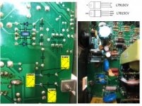
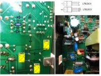
Hi everybody !
First post in this nice forum I've just discovered !
Here is my problem : my subwoofer can not turn on.
This is a Focal Cub 3 model : "BASH technology : both AB and D-class amplifier !"
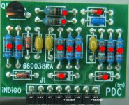
I found some weird resistors on a little pcb soldered on the main one :
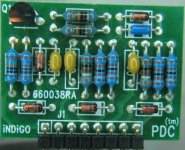
This little card seems to drive the 2 MOSFET before the main transformer.
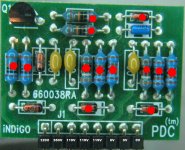
So I changed all the resitors + 3 diodes (red marks on the following picture).
You can see the measured voltages on the 8-pin little card, too:
When I try the amp => always the same problem = no square signal on the two MOSFET gate before the transformer...
Nothing on the 3 last pins. The 5th pin drives one MOSFET gate and the 8th pin drives the gate of the second MOSFET.
After measuring many voltages and signal with both my multimeter and my scope, I realized that the amp worked !!
So I measured all the voltages again : nice square waves on the 5th and the 8th pins !!!
After powering off and on the amp, nothing again...
Currently it still doesn't work...
What do you think about it ? Is it possible that I made the circuit oscillate with one of my probes ?
Which component of the SMPS could be bad ?
Thanks a lot for your help !
Frank.
First post in this nice forum I've just discovered !
Here is my problem : my subwoofer can not turn on.
This is a Focal Cub 3 model : "BASH technology : both AB and D-class amplifier !"
I found some weird resistors on a little pcb soldered on the main one :

This little card seems to drive the 2 MOSFET before the main transformer.
So I changed all the resitors + 3 diodes (red marks on the following picture).
You can see the measured voltages on the 8-pin little card, too:

When I try the amp => always the same problem = no square signal on the two MOSFET gate before the transformer...
Nothing on the 3 last pins. The 5th pin drives one MOSFET gate and the 8th pin drives the gate of the second MOSFET.
After measuring many voltages and signal with both my multimeter and my scope, I realized that the amp worked !!


So I measured all the voltages again : nice square waves on the 5th and the 8th pins !!!
After powering off and on the amp, nothing again...
Currently it still doesn't work...
What do you think about it ? Is it possible that I made the circuit oscillate with one of my probes ?
Which component of the SMPS could be bad ?
Thanks a lot for your help !
Frank.

