Gate Drive Transformer Issues

lynxlynx

A rumbling soft motor
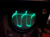
Also does it matter where wire physically starts when taking waveform signal? When I installed GDT I have beginning of wire at source of FET and end at gate. But I measured in reverse, placing ground at gate. I do see difference between simulation waveform and erroneus one I posted before.
 

Jagd.Panther

New member
Sorry I will not able to tell you now because you were right about GDT insulation. Today when testing I encountered a spark near it (maybe inside it) but it continued to work. I hope nothing damaged. I do not test it since then. I will rewind it with insulation today.
Be sure the check zeners and fets (that's a must), as well as emitter followers.

Back to back, as in my simulation.
Probe every gate and see if waveform is symmetrical (do not supply FB with HV). If it's not check that all of the zeners aren't shorted, rated for same voltage, and installed correctly.


Also does it matter where wire physically starts when taking waveform signal? When I installed GDT I have beginning of wire at source of FET and end at gate. But I measured in reverse, placing ground at gate. I do see difference between simulation waveform and erroneus one I posted before.
Ground of the probe should be connected to Source, otherwise oscilloscopes chassis would be driven with HF, and depending on probe's wire length/oscilloscope chassis capacity/stray capacity in the oscilloscope PSU the signal will be more or less distorted (not to mention it would be upside down).

WRT windings: it matters for phasing outputs, you should always take into account where winding starts and how do you wind it, CW or CCW.
 
Last edited:

lynxlynx

A rumbling soft motor
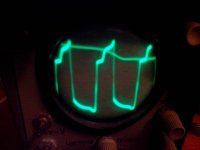
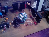
Hello, there are waveforms from my new GDT stacked from two cores. The problem is that I only have cat5 cables. Nothing that I have fits well into these cores. But the waveform looks very strange now. 5 turns heat up the core to 40C, 4 turns to 55C. I used 6 turns. One (not stacked) feels fine with 9-10 turns of magnet wire. That's all that I have. Previous one worked very well, and SMPS launched, but very thin insulation failed once as I described.
FETs are fine. I removed IRF730 then and installed IRFP450 that I have. Zeners are OK. In fact, nothing was damaged.
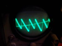
I made tests with power removed from rails and only flyback supply worked and loaded SG3525. I also attach Ct to ground waveform.
I think now I must order bigger now from internet store.

1000.jpg: high side FET
1001.jpg: low side FET
1002.jpg: Ct to ground
1003.jpg: how GDT looks.
 

Attachments

  • 1000.jpg
    1000.jpg
    32.9 KB · Views: 22
  • 1001.jpg
    1001.jpg
    31.4 KB · Views: 18
  • 1002.jpg
    1002.jpg
    28.2 KB · Views: 18
  • 1003.jpg
    1003.jpg
    74.6 KB · Views: 45

lynxlynx

A rumbling soft motor
I abandon this until I find good core. Half turns with stacked core gives strange signal, two GDTs separate ring or (with good snubber) make very audible noise, IRFP450 heatup on sinks. I am out of variants until I'll order the parts. Thanks anyone who helped!
 

Jagd.Panther

New member
Hi Lynx,

1. Ct waveform looks distorted, both amplitude and frequency is changing. Things to check: layout (interference due to high dv/dt and high di/dt, for the first one check small signal traces that are near traces with high voltage, high dv/dt traces; for the second check small loops and ground loops near loops with high di/dt), check PWM power. BTW Do you have anything connected to Pin3 of the PWM chip?

2. Probably an insulator between two cores in stacked configuration may help with heating issue. Heavy distortion could be caused by shorts in windings.

3. You can try to source hi-perm cores for GDT from old laptop power supplies (check EMI filters) or ATX power supply EMI filters. Thin multistranded insulated wire could be found in data cables for very old mobile phones

4. Since you don't have an RLC meter, I suggest you test cores like that: make test winding (5-10-15-20 turns), connect this test winding in series with low ohm resistor (like 1-2-5ohm) to some source of square wave (for example, connect it your power supply). The peak current (ignore any spikes) should be less than 100 mA.
 

Jagd.Panther

New member
4.b: another option: a royer oscillator to measure max volt-seconds the test windings and the core can handle, then adjust the number of turns to get enough safety margin for max induction.
 

lynxlynx

A rumbling soft motor
Hi Lynx,

1. Ct waveform looks distorted, both amplitude and frequency is changing. Things to check: layout (interference due to high dv/dt and high di/dt, for the first one check small signal traces that are near traces with high voltage, high dv/dt traces; for the second check small loops and ground loops near loops with high di/dt), check PWM power. BTW Do you have anything connected to Pin3 of the PWM chip?

2. Probably an insulator between two cores in stacked configuration may help with heating issue. Heavy distortion could be caused by shorts in windings.

3. You can try to source hi-perm cores for GDT from old laptop power supplies (check EMI filters) or ATX power supply EMI filters. Thin multistranded insulated wire could be found in data cables for very old mobile phones

4. Since you don't have an RLC meter, I suggest you test cores like that: make test winding (5-10-15-20 turns), connect this test winding in series with low ohm resistor (like 1-2-5ohm) to some source of square wave (for example, connect it your power supply). The peak current (ignore any spikes) should be less than 100 mA.

4.b: another option: a royer oscillator to measure max volt-seconds the test windings and the core can handle, then adjust the number of turns to get enough safety margin for max induction.

Hey Panther!

I think I now just need to halt for some time. I already ordered a set of cores to have experiments with, bigger than I have, in different shapes, they will arrive in 2-3 weeks I hope.

Regarding your interest:

1. I have pin3 floating but I had built push-pull circuits with it already and I don't have such a noise. With single GDT I even had a working quiet SMPS until spark. I don't think it's an issue. If you want I can take Ct waveform from one of push-pull circuits I have. I also checked parts on board after spark, nothing damaged.
2. I tested windings with multimeter and found no shorts, but maybe high voltage causes this. I don't know, they do not sit too tight inside.
3. I don't have much beyond a small box of old ATX PSUs and many parts (BJTs and diodes) from them. They have BJT transformers and flyback inductors but not much of them are big enough to work with. I also intended to use ring core. In beginning I tested an EMI filter ring core but it was too soft (it did not "copied" 25% duty cycle signal as much as possible, the signal was sloppy).
4. I will get one soon.
 
Last edited:

lynxlynx

A rumbling soft motor
The noise issue - can two GDTs placed nearby interfere? Especially when under high potential between windings?
 

Jagd.Panther

New member
The noise issue - can two GDTs placed nearby interfere? Especially when under high potential between windings?

No way. 99% you have poor layout or schematic.

Your new GDTs draw enough current to make them warm, and that current is likely the cause of instability due to poor layout/schematic.
 

Jagd.Panther

New member
Oh, Ct waveform looks like it's backwards. It should look like /|/|/|/| ;)

You said you have another oscilloscope, did you have a chance to try it?
 

lynxlynx

A rumbling soft motor
No way. 99% you have poor layout or schematic.

Your new GDTs draw enough current to make them warm, and that current is likely the cause of instability due to poor layout/schematic.

I disagree. Single GDT (when you said it's not safe from photo) was very good at control. It launched SMPS. The SMPS worked as intended. Some hours (at least two). I even tested efficiency. For 700W SMPS, 50W load made it 78% efficient with IRF730. The spark was random however. And I did not surprised, you warned me about insulation.
These two which are on circuit now are not heating up. But I can't even see signal on gate - it's completely distorted now. The previous unsafe one showed at least clean wave on scope (and I posted image).
My previous SMPS layouts were successful. I don't think it's layout issue. Despite I can make mistakes like anyone do, I don't think this case applies. Especially when unsafe GDT controlled FETs very well.
 
Last edited:

lynxlynx

A rumbling soft motor
Oh, Ct waveform looks like it's backwards. It should look like /|/|/|/| ;)

You said you have another oscilloscope, did you have a chance to try it?

I tend to agree. I loaded full bridge with 10nF cap and watched waveform. I expected ringing will start at beginning at peaks, but it was reversed. So you probably right. That's a surprise!
I don't have a chance to get bigger one work. It was in garage for 15 years and it's tube does not draw. I don't know why (I did not had any chance to look into it closely), I will try at least to check if it's heater is ok.
 

Jagd.Panther

New member
Lynx, "very audible noise" and unstable oscillator (you probed Ct and we saw unstable period) mean SMPS IS UNSTABLE. It may work under some conditions (steady & light load, steady input voltage) but it may (and you know Murphy's law, it will) fail under other conditions.

The main question is what triggers instability (it may be few extra milliamps drawn by GDT, few extra picofarads of stray capacitance, etc) and what's needed to stabilize the design.
 
Last edited:

lynxlynx

A rumbling soft motor
OK I'm not against it - but let's wait until more suitable and handy cores will be shipped and I will try all possible variants. Guessing from scrap without tools is painful. At least now.
 

lynxlynx

A rumbling soft motor
Hi Panther, at first I have no much suitable E cores. Or too small and difficult to use from low power ATX, or too large (for GDT) power ETD cores. I really have no many handy and ready to use small E cores. I also can only guess about their parameters (although I usually successfully use ATX ones). And when ordering, it's easier for me to get and use toroid one because my current layout does not consider any core winding shell to be used.
 

lynxlynx

A rumbling soft motor
I bought toroidal M2000NM1 that were available, but bigger: 20x12x6, 28x16x9, and B64290-L45-X87 16x9.6x6.3 N87.
4 cores of each position.
 

lynxlynx

A rumbling soft motor
I'm going to use insulation tape between each winding, that's why I buying bigger cores. Is that sufficient? I do have many 50hz transformers and I'm see no reason to buy additional copper.
 
Top