Hello everyone!
What is given:
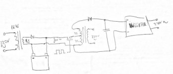
1x 24V 2600w car inverter (due to arrive in a week)
1x 1500VA UPS transformer (primary intact, 9-0-9 VAC secondary intact)
1x 600VA UPS transformer (primary might be burnt, 9-0-9 secondary intact)
1x 12V Pb car battery
I want to use the 1500VA UPS transformer to charge the battery and then power the inverter from the battery. Unfortunately, due to my lack of attention, i bought the 24v version, not the 12v.
Could I pulse the DC from the battery into the 9-0 half of the 600VA UPS transformer secondary and get the doubled voltage? Like in a autotransformer. To be more specific, the secondary has blue-brown-red wires (corresponding to 9-0-9) and i want to connect the ground to blue, pulse 12v into brown and collect 24v from the red wire (referenced to blue).
The inverter will be used to power my beast of a computer which pulls around 1200W from the wall (display included) when in full load, essentially making an active UPS from two dead UPS'.
I have access to high current mosfets, mostfet drivers, 555 timers and atmegas. Schottky diodes and low ESR capacitors are not a problem to come by around here. I personally have a cheap hobby oscilloscope, part analyser, multimeter and signal generator. For anything else, i have access to a laboratory with lots of instruments. I also am familiar with power electronics, logic, microcontrollers and programming for them.
What is given:
1x 24V 2600w car inverter (due to arrive in a week)
1x 1500VA UPS transformer (primary intact, 9-0-9 VAC secondary intact)
1x 600VA UPS transformer (primary might be burnt, 9-0-9 secondary intact)
1x 12V Pb car battery
I want to use the 1500VA UPS transformer to charge the battery and then power the inverter from the battery. Unfortunately, due to my lack of attention, i bought the 24v version, not the 12v.
Could I pulse the DC from the battery into the 9-0 half of the 600VA UPS transformer secondary and get the doubled voltage? Like in a autotransformer. To be more specific, the secondary has blue-brown-red wires (corresponding to 9-0-9) and i want to connect the ground to blue, pulse 12v into brown and collect 24v from the red wire (referenced to blue).
The inverter will be used to power my beast of a computer which pulls around 1200W from the wall (display included) when in full load, essentially making an active UPS from two dead UPS'.
I have access to high current mosfets, mostfet drivers, 555 timers and atmegas. Schottky diodes and low ESR capacitors are not a problem to come by around here. I personally have a cheap hobby oscilloscope, part analyser, multimeter and signal generator. For anything else, i have access to a laboratory with lots of instruments. I also am familiar with power electronics, logic, microcontrollers and programming for them.
Last edited: