Hi all,
All is in the title, I've joint the schematic.
How to implement short circuit protection if the driving transformer have no extra winding for this function (only 3 pins in input) and without using pins 15 and 16 of the IC?
Many thanks
All is in the title, I've joint the schematic.
How to implement short circuit protection if the driving transformer have no extra winding for this function (only 3 pins in input) and without using pins 15 and 16 of the IC?
Many thanks
Attachments
-
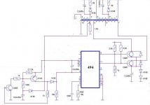 overpower.JPG38.1 KB · Views: 94

