IR2153 internal zener failure

Nixx97

New member
Recently, I built simple SMPS based on IR2153. This is first time i'm making isolated SMPS.

It's nothing more than circuit from Ir2153-s datasheet with addition of optocoupler+zener for output regulation.

It's designed to deliver +/- 50V for amplifier, with regulation, so peak voltage should be arround 66V.

First, I tested circuit without regualtion circuit, and it worked perfectly right away. Then, I connected regulation circuit as well, and it still worked somewhat fine, except for somewhat assymetrical DC output voltage.

To do some further experiments, I disconnected 1 optocouplers pin, and left 2 wires on my protoboard, so that I can connect and disconnect optocoupler when needed.

This is where issues started - after touching those 2 wires (turning regulation on) few times in a row, circuit just died - output voltage is pretty much 0V. I measured IC's supply voltage and it was arround 8,4V.

I was pretty shure that I just somehow fryed IC while probing MOSFET gates with scope, so I replaced my IC with new one.

Then, I turned regulation on again, by touching 2 wires, and IC died again. IC's supply voltage is arround 8,4V again.

Finaly, I probed IR2153-s pin 3 with scope, as well as MOSFET's gates, and it seems that IC is oscillating!?

Is there any reason why this should happen?

I even disconnected low side FET, to make shure that he's not puling down supply voltage someho.
 

Silvio

Well-known member
Show your schematic and we can discuss better.
Please note that the IR2153 is not meant to be regulated and I will tell you why when you show your schematic

regards Silvio
 

Nixx97

New member
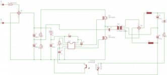
Here is quick EAGLE sketch I draw. There is no mains filter, since this SMPS was "quick and dirty" proof of concept/prototype, just to test transformer I wound and to play a bit with SMPS.
R_PROTEC is 33 ohm, approx 5W, and it seves as safety against short circuit together with 1A fuse.
Also, I live in Europe, but I got small 230->115V, 50W transformer. I'm using that to power circuit ATM, just as additional safety measure.

So, even thought this circuit is meant to work as 230VAC -> 2x50VDC converter, currently i'm using it as 115VAC -> 2x25VDC,and that's why regulating zener diode is 51V, and not 100V (wich would be required for 2x50VDC)

SMPS.jpg

Regards,
Nikola


P.S. I forgot to connect IC's pin 6 to transformer on schematic :/ but it is connected on my protoboard
 
Last edited:

Silvio

Well-known member
I cannot see the values of the components but pin 3 is not for regulation of the output.

You will be actually switching the chip on and off. You have been lucky enough not to blow your fets as well. Do not forget this chip does not have a soft start and every time it switches on it has to charge the secondary caps. One other important factor is that if pin 3 is not fully pulled to ground there will be a tendency of the frequency of oscillation will go low. This will make the transformer saturate in some instances and blow your fets. Due to what I explained so far it is a must that this pin will either be left alone or if pulled to ground will be latched for some time.

One other approach to this is by pulling the supply pin 1 to ground instead. be also careful not to make the bootstrap capacitor too large I think for the fets used if i saw correctly IRF840 between 0.5 to 1uf is enough and see that it is a good quality one.

Looking at the data sheet of the IR2153 it can be seen that there is a small voltage variation between switch on and switch off of the IC. I am trying my memory now but if I am not mistaken the shut off voltage is around 8v and switch on is around 9.6v. This gives some time between switching cycles. The shut off and on has to be done sharply here and a steady supply voltage to pin 1 must be maintained at all times other wise the fets will run in linear mode with lack of adequate current and tend to shoot through and blow. I am talking with my own experience now,

Well to conclude things the IR2153 is meant for a ballast for some neon tube but trying to do other things with it is not so easy. As for the amplifier well you do not really need regulation here and a good design in your traffo will keep the voltage quite stable. Music does not pull a steady load and the high frequency of an smps fills back up the capacitor bank around a 1000 times quicker than a normal iron trafo at 50Hz. This will help maintain the peak voltage and also not much capacitance is needed.

I hope that helps

Regards Silvio
 

Nixx97

New member
As for the amplifier well you do not really need regulation here and a good design in your traffo will keep the voltage quite stable. Music does not pull a steady load and the high frequency of an smps fills back up the capacitor bank around a 1000 times quicker than a normal iron trafo at 50Hz. This will help maintain the peak voltage and also not much capacitance is needed.


Thanks for reply and help!
I guess that I will do exactly that - unregulated supply.
I wanted regulated supply to keep maximum power output stabile and independant of mains voltage fluctuations. Oh well, "classical" mains frequency transformers have that same issue too, so I can live with that.

I will most likely use this PSU with stereo IRS2092 based class D amp.

Still, I dont quite get why Zener would fail,and not whole IC - as I said, at pin 3 I can still see capacitor charging/dischargning waveform,so rest of IC seem to work somewhat fine :/

Nikola
 

Silvio

Well-known member
Well regarding the supply pin 1 you may think its the zener well there is a lot more than a zener inside the chip. You can try to supply the chip with an external supply and see what happens. try not to exceed 15v with this voltage.

If you want to build an smps I have a link for you and see if you like it. The full pdf file is in post #13 which you can download.

http://www.diysmps.com/forums/showt...s-700w-(IR2153)&highlight=audio+smps+700watts

regards Silvio
 

Nixx97

New member
Thanks for suggestion!

Since there is no need to re-invent the weel,I will probbaly adopt Your schematic, with some tweaks/simplifications.
Most likely, I will simplify IC's 12V supply rail a bit, but that depends on how much space I will have on my PCB(I will have to make my own design) and some other minor factors.

I am thinking about removing short circuit protection as well, since IRS2092 has got its own protection circuitry, but that might not be the best idea.

Nikola
 

Silvio

Well-known member
Thanks for suggestion!

Since there is no need to re-invent the weel,I will probbaly adopt Your schematic, with some tweaks/simplifications.
Most likely, I will simplify IC's 12V supply rail a bit, but that depends on how much space I will have on my PCB(I will have to make my own design) and some other minor factors.

I am thinking about removing short circuit protection as well, since IRS2092 has got its own protection circuitry, but that might not be the best idea.

Nikola

Its your choice Nicola but be careful as if you have high capacitance on the output of the smps the switching transistors see near a dead short for an instant and if there is no form of current limit there will be a chance of blowing your fets. The IR2153 has no soft start.

If you put an inductor on the output it will limit current during the initial charge up. But this is not really needed as the smps runs at full duty and noise is not that bad. An inductor on the output will create voltage drop at load.

The current limit adopted in the circuit works as a soft start while charging secondary caps. The smps can even start with a load connected

Regards Silvio
 
Top