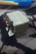
Hi, I have built my first SMPS. I use IR2153 oscilator 50 kHz and 2x EE4215 ferrite core. Primary turn 40 turn (0.5mm 3 strand) and secondary turn 4 turn (0.5mm 8 strand).
My first target is only 15V 20A, but when I attach load (DC Vacum Cleaner 12V 100Watt), output current only 3.5A.
What's wrong with my SMPS? Please help.
Thank You.
My first target is only 15V 20A, but when I attach load (DC Vacum Cleaner 12V 100Watt), output current only 3.5A.
What's wrong with my SMPS? Please help.
Thank You.
Attachments
-
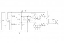 IR2153 (15V 20A).jpg116.2 KB · Views: 183