IR2153 smps with short circuit protection.

Bettecher

New member
Norazmi,

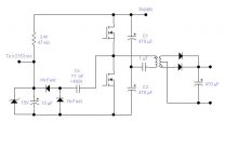
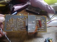
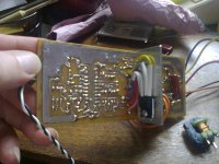
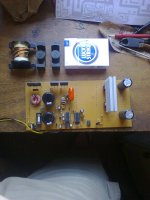
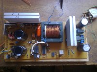
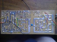
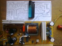
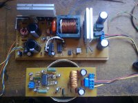
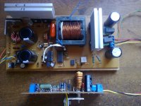
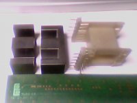
No, at this time I’m using a resistor to feed the IR2153 but the next design I’ll use a extra turns form the transform in order to increase the current to drive the IRF460LC stead of IRF740. The weekend is coming and I’ll take some pics and post here. For this time, here’s a pdf from the board.
Thanks!
 

Attachments

  • Board_01.pdf
    343.1 KB · Views: 1,961
Last edited:

norazmi

diysmps Senior Member
nice, oh.. , i did test experiment in real, using clamp supply ir2153 by resistor feed to zener it will hickup at peak current when u push hard. even im using irf740 so if using irfp460 will be more demanding supply at ir2153 vcc. I think its because high voltage also drop and it will effect ir2153 supply since we take the power from same source. So what i did, there will be 2 solution, 1. using additional supply from main trafo and limit with LM7812, 2. using external supply.

Yeah please post some picture here :D . Btw irf740 is good up to 600 wrms and 800wrms peak with proper trafo winding.
 

norazmi

diysmps Senior Member
bet what is your fsw? and +/-12 supply ur using resistor clamp with zener diode, i think resistor should be lower to 470 ohm 3 watts. What is your secondary output supply? If below +/- 50 vdc and the dummy load 10kohm is high, lower it to 3.3k 2 watts.
 

Bettecher

New member
You’re right. when the supply dropped, the ir2153 turned off because the internal undervoltage lockout circ. There is another solution. Value of “Cx will control the max. available current.
 

Attachments

  • Supply.JPG
    Supply.JPG
    19.2 KB · Views: 867

Bettecher

New member
Norazmi, my new trafo is not already but, I did run a test today using an old trafo that was made before rated to 500w and believe or not, I successfully extracted 630 watts! 70+70 x 4.5 amps.
Everything warm up a little bit but, not too much.

By using my formulas, here are the results for my new trafo:

Fs = 80 Khz
Min. Ac input = 90vca = (2.28 * 90) ' for 90 vca = ( 205.2 VDC ) worst case!
Vo = 50 + 50
Io = 10 amp.

Ps = 1000 Total power

B = 1500 Gauss
J = 319
Kj = 397
Ap = 5,1 Min. Area product required

I’ll use core EE - 42/21/20

Ap = 6,14 ( Aw * Ae ) cm4
Ae = 2,4 (Ae) cm2
AL 5800 (Al) cm2

Main results are:

Ip rms = 8,186 amp.
Is rms = 14,14 amp.

Apri = 0,0256 - Acu Prim. (Cm2)
Asec = 0,0443 - Acu Sec (Cm2)

Np = 16 - Prim. turns - wires = 40 x 29 awg - (Skin effect)
Ns = 7 + 7 – Sec. turns - wires = 34 + 34 x 29 awg.

What do you think about that? Please, let me know.
 
Last edited:

Bettecher

New member
Here are some pics from my last 1kw spms based on IRF460, IR2110, SG3525, TL431 and optocoupler PC817. As you can see, there are too many components, that’s why I decide tried the IR2153. The design is working very well and one channel of my D class amp is included. Hope you like!
 

Attachments

  • Foto0006.jpg
    Foto0006.jpg
    1.1 MB · Views: 511
  • Foto0007.jpg
    Foto0007.jpg
    402.4 KB · Views: 410
  • Foto0045.jpg
    Foto0045.jpg
    360.3 KB · Views: 434
  • Foto0067.jpg
    Foto0067.jpg
    409.9 KB · Views: 510
  • Foto0070.jpg
    Foto0070.jpg
    426.1 KB · Views: 377
  • Foto0075.jpg
    Foto0075.jpg
    373.9 KB · Views: 389
  • Foto0076.jpg
    Foto0076.jpg
    1.1 MB · Views: 471
  • Foto0077.jpg
    Foto0077.jpg
    1.1 MB · Views: 426

MicrosiM

Administrator
Staff member
Here are some pics from my last 1kw spms based on IRF460, IR2110, SG3525, TL431 and optocoupler PC817. As you can see, there are too many components, that’s why I decide tried the IR2153. The design is working very well and one channel of my D class amp is included. Hope you like!


Very nice job friend Bettecher.

It would be great to see some testing results of your SMPS, as I can see that's a regulated version?

How much voltage drop you have at 500W load?


Do you have an oscilliscope to inspect some waves?


Regards

:UP:
 

norazmi

diysmps Senior Member
E42 u can get 1kw> through it. lol your coils winding is good by using strand wires. I believe that ur primary turn is 8+8 which total is 16, may i suggest with fs= 80 Khz u can lower the turn by 14 or 12. by adjusting primary winding u need to watch out secondary output per turn.

p/s - can u post the class D schema u have made? :D
 

Bettecher

New member
Very nice job friend Bettecher.

It would be great to see some testing results of your SMPS, as I can see that's a regulated version?

How much voltage drop you have at 500W load?


Do you have an oscilliscope to inspect some waves?


Regards

:UP:

Thanks MicrosiM, Answer your question:

The circuit is based on TL431 and I don’t have any voltage dropped until 800w when the short protection circuit starts to limit the current smoothly. ( I do not use the shutdown pin.) It’s done by reducing the duty cycle. Yes, I have an old 100 mhz four channels oscilloscope and if you want I can post here any test, just give me time for that. I also can provide de schematic if you need!

Regards
 

Bettecher

New member
E42 u can get 1kw> through it. lol your coils winding is good by using strand wires. I believe that ur primary turn is 8+8 which total is 16, may i suggest with fs= 80 Khz u can lower the turn by 14 or 12. by adjusting primary winding u need to watch out secondary output per turn.

p/s - can u post the class D schema u have made? :D

Norazmi, the class D schematic is the same of iraudamp7d and you may easily find on the net but, if you want I can post here, sure!
 

Bettecher

New member
In order to make some of you happy, here’s the schematic of my 1kw smps.
This is the same based combination of IR2110 and SG3525 but, has lots improvements like a linear short circuit protection, better response of output transients, high output peak current and voltage regulated. Specially designed for audio applications.
Enjoy!
 

Attachments

  • Esquema Revisado_05.pdf
    389.9 KB · Views: 2,103
Top