IR2161 smps

Silvio

Well-known member
Hello fellow friends, has anyone tried this chip as an amplifier smps?
I can see that it has a soft start and also a short circuit protection. I found someone on youtube comparing the IR2153 with this chip. unfortunately it was in Russian and did not understand a word he said. The IR2161 is basically a halogen driver chip but I was wondering if it could be adopted for an amplifier smps. Anyone with better knowledge than me may say something about this chip. I am also posting the PDF data sheet.

I could see from the data sheet that it is a half bridge driver and could sink and source around 500mA on its output driver. Maybe just right for driving a couple of large fets such as the IRFP450/60 etc. It is also capable of dimming the halogen lamps it is driving. It drives in ZVS hence making little EMI. A lot of options could be made with this chip and maybe it could be driven with a PFC to control the output voltage. It is just my taught about it. I guess its worth considering building something useful for us.

I await some comments from your end.

Regards Silvio.

View attachment IR2161 datasheet.pdf
 
Last edited:

alertlink

New member
It looks interesting. I'll look for IR2161 in my local market.

That Russian project video consists of 3 parts, they consider the theory, assembly and testing of ISPs at 2161. It has a project page and also discussed in forum.

Here, it is translated

IR2161 VS IR2153. Switching power supply for IR 2161

This article will be of interest to those who collected ISPs based on IR2153. In fact, the IR2153 is poorly suited for creating an SMPS, due to the lack of a full-time protection system against short-circuits and overloads, the impossibility of "dimming" if necessary and creating feedback on voltage and current.

More suitable for creating the IR2161. This is a semi-bridge pulse converter for feeding halogen lamps. Features 2161 - protection against overload and short circuit with automatic reset, soft start, the possibility of dimming (in several ways), the ability to build feedback. After the construction of input and output cascades, an impulse power source is obtained.
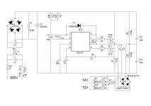
Here is the scheme of the ISP on 2161.
2161.JPG
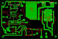
Layout for the pcb ,
lay.JPG

The power supply and current of these chips are approximately the same, so you can use the 2161 power scheme for 2153 on R2 and R3 resistors of 2 W, you can use the Chinese "brick" 5 W at 18-30 kΩ.


On board 2161 there is a soft start function (softstart). It works like this: immediately after starting, the frequency of the internal clock of the chip is about 125 kHz, which is much higher than the operating frequency of the output circuit C13C14Tr1 (about 36 kHz), as a result, the voltage on the secondary winding T1 will be small. The internal oscillator of the chip is controlled by voltage, its frequency is inversely proportional to the voltage on the capacitor C7. Immediately after switching on, the C7 starts charging from the internal current source of the chip. Proportional to the increase in voltage on it, the frequency of the chip generator will decrease. When reaching 5V (about 1sec.), The frequency will decrease to the operating value, about 36kHz, and the voltage at the output of the circuit will accordingly reach the nominal value. Thus, a soft start is realized, after its completion, IC1 goes into the operating mode.


CS pin (pin 4) IC1 is the input of the internal error amplifier and is used to monitor the load current and the output voltage of the half bridge. In the case of a sharp increase in the load current, for example, in the case of a short circuit, the voltage drop across the current-sense resistor R7 will exceed 0.56V, and therefore on the output.4 IC1, the internal comparator will switch and stop the clock. . In the apron and datashete there are calculations of the R7 current-sensitive sensor. The conclusion can be made immediately 0.33 ohms - 100 watts, 0.22 ohms - 200 watts 0.1 ohms-300 watts, did not test, but you can try 2 resistors in parallel on 0.1 ohms - then the maximum load will be 400 watts. The test of protection against short-circuit I showed a video. In more detail, the operating modes of the IR2161 chip are discussed in the datasheet.
Condenser C3 with a capacity of at least 1μF per 1W output power. With such a capacitor, the NTC1 thermistor must be used, for example from a computer power supply.


You can make the transformer calculations, you can take it ready, but I decided to wind it on an unknown ferrite ring of 29 mm. I declined the calculations, because This is the half bridge and the other end of the bridge are capacitors C13C14, - you can make a mistake by 200%. The primary was wound with a wire 0.5 mm in diameter. Completely filled the ring with about 80 turns, secondary lits in 4 wires 0.5 mm per eye, bipolar on 24V, 2 to 12V. Examples of transformer calculations are present in the apron and datasheet.


Files,
http://radiokot.ru/circuit/power/supply/51/01.zip

Website,
https://translate.google.com/transl...u=http://radiokot.ru/circuit/power/supply/51/
Forum,
https://translate.googleusercontent...4809ac&usg=ALkJrhikuY_kV97goocJ2eFSM2-b12L4Xw
 
Last edited:

Silvio

Well-known member
Hello alertlink, Thank you very much for your feed back. In fact I have been watching again the videos you mentioned and used the translated captions on youtube I could understand a bit as the translator on youtube tends to say things that would not make sense at all.

With the site you given me I will follow the tread and will surely understand better. I also read the data sheet properly and understood most of its functions. It looks a very promising chip to work with making an smps with few components. I will probably adapt the start up circuitry that I used previously with the last smps I published (audio smps 700w with IR2153) and will experiment a bit with this chip. The only mishap is that it has a fixed frequency and cannot play with it much but with 36Khz is not so bad either. I usually go a bit higher than that try to squeeze some more power of the core but that will have to do with a fixed frequency.

I looked for it on E-bay but the cost is not so cheap. I also took a look in Aliexpress and found it at a reasonable cost. I will be purchasing some of them.
Experiments have to wait for after summer as by this time of the year I will be busy repairing air conditioners but as fall will come I will have more spare time.

Once again I thank you for the explanation and also for the material you given me. I will surly will not let you down and around September or October I will come up here with some results. I hope DIY ers will find it useful.

IF ANYONE WISHES TO EXPERIMENT WITH THIS CHIP IS FREE TO DO SO. TOGETHER WE SUCCEED AND SHARE OUR EXPERIENCES IN A USEFUL SMPS

Regards,

Silvio
 

Silvio

Well-known member
Hi I looked at the first 10 pages of the tread and it seems that when the output of the transformer is coupled to an output bridge and capacitors things started changing like frequency shifting down with load and a lot of other queries.
Soft start not working as it should on all loads and other things like current sense not working accurately. This chip is rather intended to drive halogen lamps with an AC output voltage. Trying to modify seems to disturb the whole thing and not getting quite there.

As for myself from what I seen I will still prefer the IR2153 not having a soft start, short circuit and also voltage regulation. Well I found a way with current limiting and soft start. The IR2153 being a very cheap chip ment for a ballast still can do a lot of things. On the other hand if one wishes to have a regulated smps must opt for a chip meant for this reason.

Regards,

Silvio.
 

scormonel

New member
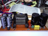
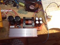
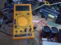
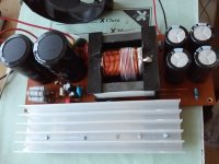
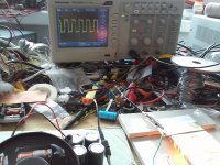
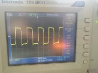
I made a SMPS with IR2161. I have a sample wiring, the project is not finalized and is in the measurement phase. I am unhappy with the fixed frequency that is real about 27Khz at my integrated. I used IR2161 SMD. I wait for 0.1 ohm and 2W resistors to put about 5 pieces in parallel on the current limitation to see how much power it can get. We have planted a resistance of 0.22 ohms at the moment.
1500W.jpg20170706_001832.jpg20170706_001857.jpg
 
Last edited:

scormonel

New member
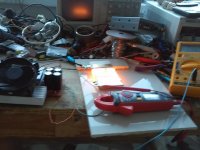
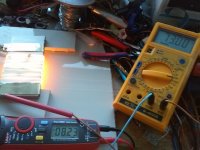
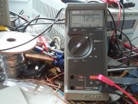
I put the resistors in the overcurrent protection. We found that the frequency increased to 42Khz. When the voltage drops on the resistance at the bottom MOSFET source, the frequency decreases. I put a load resistance that passed a current of 8.23 amps. The output voltage dropped from 80 volts to 73 volts in load. Secondary diodes are 16 amperes but we did not have the larger load.

0.02_OHM.jpg Target_resistance.jpg POWER.jpg
 

MicrosiM

Administrator
Staff member
@Scormonel

Your test results looks good, I recommend that you increase the switching frequency to at least 62KHz.

I don't recommend to use the method "resistors" to sense the current into your circuit. Use current transformer.
 

Silvio

Well-known member
Hi Microsim, I do not think that the frequency can be changed with this chip as it is set internally. I had been reading in the Russian blogs that frequency tends to change a bit with load. I guess the trafo need to have calculated windings for around 30Khz or so. I am not sure what power an etd49 can give at this frequency. I guess it would around 700 to 900 watts at the most. Having this frequency also gives a chance to use 0.7 to 0.8 mm wire for winding the trafo. This will make life easier for current handling.

Hi Scronmel I do not know what output voltage are you aiming for as in the first pics I saw 160vdc is it input or output voltage? In the second set of pics I saw 80 volts. Keep in mind that your calculations if you have a stabilized voltage on the output you will be needing around 20 to 28% more headroom especially if you also have output inductors fitted. Things have to be considered that we are measuring peak voltages, and even at the input of the smps peak DC voltage also drops with load. Loading the smps the voltage will sag a bit in the ripple current. Do not compare things with an iron transformer psu as the input voltage will be stable being ac and voltage drop occurs only on the output rectified and smoothed voltage. I do not know what are your intentions for using this smps if its for audio or something else.

Regards Silvio
 

scormonel

New member
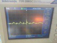
The SMPS I built it to power an audio amplifier. The IR2161 can not set the frequency, it is fixed and internally set. As I wrote above, I found that the frequency depends on the voltage drop on the current detection resistance and are inversely proportional. Overcurrent protection, so implemented by IC and I leave it. We used 1mm wire winding, two in parallel in the primary and three in parallel in the secondary. The 160V voltage was between + and -. The voltage of 80V is the voltage rectified and 73V is the rectified voltage in secondary at the current of 8,23A. Output inductors I have not and I will not put, so I built all the SMPSs so far and I had no problems. I'll put the oscilloscope on the secondary and post the results here.
 

Silvio

Well-known member
Hi Scormonel, I think your winding wire is a bit thick for the frequency being used. The diameter for the copper wire according to my chart is as follows:-
1mm up to 17Khz, 0.91 mm up to 21Khz, 0.8 mm up to 27Khz, 0.7 mm up to 33khz, and 0,65mm up to 42Khz. As you can see with the frequencies I see on your pics your wire is a bit thick and skin dept is not using all the copper in your winding.

If your smps is used for audio then 6 amps per mm^2 can be calculated for the copper winding.
The smps has no feedback for voltage regulation but does it by lowering the frequency and inducing more magnetic field in the core due to the higher B when the frequency lowers, this is rather a crude way but seems to work. Consider also that the chip is designed for driving halogen lamps of 12 or 24v. Taking some percentages we can see that when using only say 12 and subtracting 10% we get around 11v at 8 amps load (96 watts). It does not seem much. Bringing up the voltage to 80 and subtracting 10% from it brings a voltage of 72 volts for the same current draw 8A,(572 watts) I do not think that your result is that bad. I also think that if you use thinner copper wire and a cross sectional area according to 6A/mm^2 the performance may improve due to having lower losses in the copper and AC resistance.

On what operating frequency you made your winding turns calculation? What is your target output power for this smps?
One last comment Music does not consume continuous load and only takes more or less from 30 to 60% This will give time for the output caps to reach their full voltage again, Why not try it out on the amp and see what happens?

Regards, Silvio
 

scormonel

New member
Hello Silvio
All the calculations we made for 34Khz, frequency given by the integrated circuit manufacturer in pdf. I used two copper wires of 1mm in parallel and in the secondary three copper wires of 1mm in parallel. I coiled the six-wire copper thread 1mm at a time. The power I hope to get is 1500W. I know from previous experiences that an audio amplifier is a much more relaxed task than a resilient task. But with large diameters on the copper wire, I think the losses will be offset. I intend to set it up and then make several pieces because I found IR2161 at stock liquidation and convenient price at TME and I took 40 pieces. In this integrated circuit I do not have access to the oscillator and neither PWM has it, so it is excluded that I can make a feedback to stabilize the output voltages. But I was attracted by the output capability of managing + - 500mA. This is a prototype. Up to the final version and PCB is a lot. I'm trying to see what I can get.
Good health !
 

Silvio

Well-known member
Hello Scormonel, I made an SMPS using ETD49 N87 core driven by SG3525 and IR2110. The switchers used where 2X IRFP460. I tried 2 different windings one with litz wire and the other with 0.5mm copper wire. The switching frequency was 60Khz and the peak power absorbed was around 1200 watts after that I was experienced severe voltage drop. The current density of the wire was calculated at 6A/mm^2 in both versions.

I am saying this because I doubt it if you can get 1500W from the core at 30Khz and I guess you have to use a bigger core.

Well what I can see from your wire thickness you are a bit under rated in the secondary winding CSA (1mm)of wire X 3 = 0.785mm^2 X 6A/mm^2= 4.71 amp per wire so now is multiplied by 3 wires we get 4.71 A X 3 = 14A. Power = 14A X 80v = 1120 watts. In the primary you are just under 1500 watts with the same calculation using 155v X 9.42A.

I am also posting another PDF related to the chip maybe you can add some other features like feedback etc

Regards Silvio

View attachment an-1069.pdf
 

scormonel

New member
Hello
If you used SG3525 and IR2110, I do not understand why you will not go to 300-400kHz. Who prevented you? With IR2153 at 75kHz, a transformer from an ATX source with the original 36-pole coil and wire as it was I did not know, I pulled 1000W with 2 H15NB50FI MOSFETs of 15A, 500V and 0.36 ohms. But all the source in the original PC case and ventilated with the original cooler. But let me come back. On samples we have used a cooler that blows all over the source. Without it, the radiator heats up hard, reaching 81 degrees, especially in the secondary diode area. I'm convinced I can get a lot more power. Remains to be seen. I must somehow resolve with the load resistance to pull a serious stream from the source. In the evidence we loaded with the consumer only the positive tension, the negative one remaining unused, situation that can be seen on the oscillogram, on the negative alternate there is a peak. And here they use the same H15NB50FI transistors manufactured by ST that we found very cheap at a stock clearance and took 200 pieces.
Regards.
Ionel
 

Silvio

Well-known member
Hi Ionel, I could have rise up the frequency more but what about switching losses and core losses? My smps could hold a 900 watt load all day as I fitted a cpu heat sink to the diodes and the switchers. The draft from the cpu heat sink also cools the trafo and output inductors. My tests where carried out on the full winding and I was a bit aware of setting the short circuit protection higher as I was not so confident at that time. Now its adjusted to trip at around 1500 watts (11A) If you want to take a look you can find it on this website.
There is also a video of the load test found here https://www.youtube.com/watch?v=18l-plvqkdU
The tread for this build is here. http://www.diysmps.com/forums/showthread.php?872-1000w-smps-based-on- &highlight=1000w+smps.
The full detail pdf file is found on post #12

Loading your smps you could use heating elements and halogen lamps like I did. Even a heater from an old kettle or water heater.

About the ATX trafo its rather amazing pulling 1000 watts out of an EI33 core. Just one question how long could it withstand it? What was your voltage drop at this load?
My last question is do you intend to mass produce it? I asked the last question because you bought a lot of transistors etc.

Regards Silvio
 

scormonel

New member
Hello Silvio
I studied your project with SG3525 and I am impressed. Congratulations! I really liked the idea with the overcurrent protection comparator. I have some attempts with SG3525 but I will not use the IR2110 driver which is expensive. When you play with them, you sometimes ruin them and do not want to burn in my pocket, I use what is cheaper. I tried with a transformer but the result is not thankful. The waveform does not look too good. I probably do not have enough inductance, I will try with a bigger transformer. As for the ATX transformer source, I mounted it in a 2X400W class D amplifier and it has been operating for over 2 years. I do not intend to produce it in the mass but I never liked it when I needed something to wait for a week to come. In my city there are very high prices for components and I buy only online and hundreds of pieces. When I start something, I like to have everything ready. For many years, they no longer use classical transformers for the amplifiers that build them. Only switching sources.
 

Silvio

Well-known member
Hello Ionel, for the purchase of the IR2110 you can find the link here and 5 of them do not cost much.

Link https://www.ebay.co.uk/sch/m.html?_....TRC0.A0.H0.Xir2110.TRS0&_nkw=ir2110&_sacat=0

I purchased these and they worked fine.

If you want to build the smps I guess the one from LUDO 3232 (you can find it on diysmps forum) is simpler than mine as you can find parts for it more easier. The version I built was based around what I had in the junk box. I used the same schematic of Ludo to build mine. I only included the +/- 15v , the fan output and the output inductors for mine.

I suggest to you that you also read the blog posts on this site regarding transformer winding practices and Making litz wire at home. These blogs carry useful information and can guide you to making a safe transformer and adequately spaced pcb. I also made a video which can be found on youtube it is called winding small transformers for smps. This video is also very informative. You should be aware that if the primary of the smps trafo leaks with the secondary it will present the grid voltage at the secondary and can kill you. This is why we always have to at least capacitively couple to the earth ground the primary and secondary windings. If you take a close look at my schematics and PCB you will notice that.

I always preach about this because there are a lot of new comers and do not realize the hazard. We here on diysmps cannot be responsible for any errors or mistakes of unskilled members. That is why I provided information.

As far as the pulse transformer, well it has to be designed well and it also needs to have enough current to drive the mosfets.
The IR2110 has a capability of 2Amps in its output driver and its very robust. Regarding the switching frequency well you have to be careful with the bootstrap cap so that it has time to charge up between pulses and giving adequate current. However when using a bootstrap arrangement voltage regulation of the output is somewhat limited due to the bootstrap cap not charging enough during a short pulse width. However using a pulse transformer will give better performance in this regard especially if it has its primary winding enhanced with a lure winding in the main transformer to boost up the current.

Prevention of blowing up chips. I always try out the oscillator section alone by driving a couple of leds and check operation with an external power supply with current limit. I can check wave form, frequency, dead time etc. and see that all is well before I try to drive the fets. This will save components and not putting any holes in your pocket.

Regards Silvio
 

scormonel

New member
Good Silvio
I avoid buying the semiconductors on ebay and aliexpress because I had unfortunate experiences. Fueled, they clicked first and the Farnell component was the same fitting, it worked perfectly. Even the condensers you buy online do not have the enrolled value, but they are approaching half.
In transformers I put very good insulation and between the primary and secondary masses put a resistance of 10 megaohms to prevent electrostatic charges. I do not like to put capacitors because it's running the secondary mass. If I buy the driver, I'll give the money on the L6491 from ST that can charge and absorb 4A. When the boot strap capacitor is too small, the oscilloscope is immediately seen as the top of the waveform is tilted. That's what happens to me when the transformer does not have enough energy stored to keep the mosfet open for the entire drive. Normally I try the small signal side before attacking the MOSFETs. Waveforms are accurate to samples, but when attack ends, the waveform does not look good anymore, although a faulty feed is excluded because it uses a stabilized laboratory source for samples. When I get to a version that will please me, I will post here. I also have two movies with my attempts.
All the best!

https://www.4shared.com/video/ytCAvt...OFT_START.html

https://www.4shared.com/video/52iD49pjca/gata.html
 

scormonel

New member
The first link makes figures
[video]https://www.4shared.com/s/fytCAvtFGei[/video]
 
Last edited:

Silvio

Well-known member
Keep up the good work. I have seen the videos and the soft start in the video in your last post seems to be functioning well

Regards Silvio
 
Top