hi everyone.
my first post here.
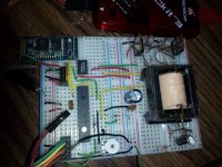
here's my setup; a microchip pic16f1783 outputs a push-pull pulse train from its psmc module (programmable switch mode controller). at the moment, its on breadboard for testing purposes first.

input is 12vdc, into the etd29 size transformer, (or etd19 ?) yanked out of a old computer power supply. its rewounded with 2 x 12 turns primary, and 1 x 9 turns secondary 0.7mm wire.
i can change/programme different values of duty cycles, from 1% to 25%. output from pic is fed into a tc4424 dual mosfet driver, driving 2 x irfz44v, connected to the push pull primary windings. frequency is ~ 45khz. here are the scope images:
View attachment 2222.bmp View attachment 3333.bmp
4.61% duty produces 9.6 volts.
25.3% duty produces 10.0 volts
my question; is this tiny variation in voltage (0.4v) ,between the two different duty cycles(4.6% and 25.3%) normal?
i was expecting a much bigger range/difference in output voltage. at least 5v, since im trying to incorporate voltage feedback.
this is just an experiment to get my feet wet, before i jump into the mains voltages smps. current limiting is working great.
thanks for reading.
my first post here.
here's my setup; a microchip pic16f1783 outputs a push-pull pulse train from its psmc module (programmable switch mode controller). at the moment, its on breadboard for testing purposes first.

input is 12vdc, into the etd29 size transformer, (or etd19 ?) yanked out of a old computer power supply. its rewounded with 2 x 12 turns primary, and 1 x 9 turns secondary 0.7mm wire.
i can change/programme different values of duty cycles, from 1% to 25%. output from pic is fed into a tc4424 dual mosfet driver, driving 2 x irfz44v, connected to the push pull primary windings. frequency is ~ 45khz. here are the scope images:
View attachment 2222.bmp View attachment 3333.bmp
4.61% duty produces 9.6 volts.
25.3% duty produces 10.0 volts
my question; is this tiny variation in voltage (0.4v) ,between the two different duty cycles(4.6% and 25.3%) normal?
i was expecting a much bigger range/difference in output voltage. at least 5v, since im trying to incorporate voltage feedback.
this is just an experiment to get my feet wet, before i jump into the mains voltages smps. current limiting is working great.
thanks for reading.
