boriszarkov
New member
Hello,
I trying to design and build solid state LASER Constant Pulse Power power supply, based on Buck converter topology.
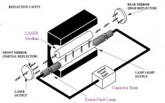
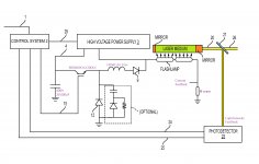
The principle of operation of those type of LASER:
1 Charge Capacitor bank
2 Discharge Capacitor through Xenon flash tube
3 Emitted light from flash tube cause Simulated emitting of light radiation in LASER media
4 Radiated light from LASER media amplifies trough laser mirrors (resonator)
5 Amplified light exits LASER resonator
The most important moment for the control of the output of the LASER is controlling capacitor discharge across the flash tube.
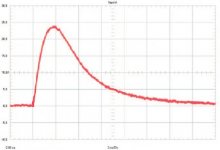
UNCONTROLLED DISCHARGE /Connecting flash tube directly to capacitor bank/
If uncontrolled discharge occurs, the current, that flows through flash tube and therefore the output light achieve peak pattern across time.
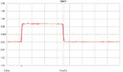
CONSTANT CURRENT DISCHARGE /Connecting flash tube to capacitor bank through current controller/
if constant current discharge occurs through flash tube and output light stays constant, which is actually our desired effect
another problem comes with uncontrolled discharge and this is flash tube output light spectrum alteration, which is highly undesired effect, so this is another reason we want constant current discharge.
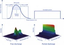
Since electrical discharge duration is approximately 30mS and discharge current is couple of hundreds Amps, I have to build constant current /power/ Very High Peak power Buck converter to obtain control of discharge. For most accurate feedback best approach is to use output light intensity or current through lamp. So I have find some reference designs and start to thinking...
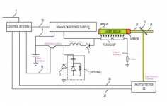
In my design I will use current feedback, so optical output measuring system will have mostly calibration purpose.
In summary - I have to build a Buck converter with following characteristics:
Input Voltage 300 - 400 V
Output Voltage* 100-200 V --> I have to make more accurate calculations
Output Current 300-600 A
Pulse duration 30mS
Output ripple +/- 20% or even more
It apparent to be very difficult design for my, so I decide to ask help from most advanced SMPS forum.
For now i have chose some of components:
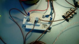
1. IGBT Switch:BSM400GA120DLC because I have it in home and think it is suitable for application
2. Coil 100uH Air cored - I chose air core because I thing it will be cheaper than ferromagnetic cored
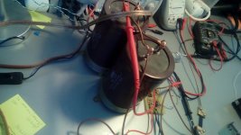
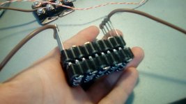
3. Capacitor bank of 20 000uF at 500V
I have doubts for :
1. Topology - is it good idea to use different topology since I need high reliability and not interested about efficiency
2. Buck controller IC - specialized Buck controller, generic PWM controller, or PFC controller.
3. Switching frequency - I suppose 20 - 40 KHz are suitable.
4. Do I need output capacitor, since application can take huge ripple voltages?
I will highly appreciate any help.
Best regards
I trying to design and build solid state LASER Constant Pulse Power power supply, based on Buck converter topology.

The principle of operation of those type of LASER:
1 Charge Capacitor bank
2 Discharge Capacitor through Xenon flash tube
3 Emitted light from flash tube cause Simulated emitting of light radiation in LASER media
4 Radiated light from LASER media amplifies trough laser mirrors (resonator)
5 Amplified light exits LASER resonator
The most important moment for the control of the output of the LASER is controlling capacitor discharge across the flash tube.
UNCONTROLLED DISCHARGE /Connecting flash tube directly to capacitor bank/
If uncontrolled discharge occurs, the current, that flows through flash tube and therefore the output light achieve peak pattern across time.

CONSTANT CURRENT DISCHARGE /Connecting flash tube to capacitor bank through current controller/
if constant current discharge occurs through flash tube and output light stays constant, which is actually our desired effect

another problem comes with uncontrolled discharge and this is flash tube output light spectrum alteration, which is highly undesired effect, so this is another reason we want constant current discharge.

Since electrical discharge duration is approximately 30mS and discharge current is couple of hundreds Amps, I have to build constant current /power/ Very High Peak power Buck converter to obtain control of discharge. For most accurate feedback best approach is to use output light intensity or current through lamp. So I have find some reference designs and start to thinking...

In my design I will use current feedback, so optical output measuring system will have mostly calibration purpose.
In summary - I have to build a Buck converter with following characteristics:
Input Voltage 300 - 400 V
Output Voltage* 100-200 V --> I have to make more accurate calculations
Output Current 300-600 A
Pulse duration 30mS
Output ripple +/- 20% or even more
It apparent to be very difficult design for my, so I decide to ask help from most advanced SMPS forum.
For now i have chose some of components:
1. IGBT Switch:BSM400GA120DLC because I have it in home and think it is suitable for application
2. Coil 100uH Air cored - I chose air core because I thing it will be cheaper than ferromagnetic cored
3. Capacitor bank of 20 000uF at 500V
I have doubts for :
1. Topology - is it good idea to use different topology since I need high reliability and not interested about efficiency
2. Buck controller IC - specialized Buck controller, generic PWM controller, or PFC controller.
3. Switching frequency - I suppose 20 - 40 KHz are suitable.
4. Do I need output capacitor, since application can take huge ripple voltages?
I will highly appreciate any help.
Best regards
Last edited:

