LM324 Bench PSU

I made a lot of progress using the pic16F877A, the menu and software is stabilized and working with a rotary encoder. Right now its working in pure voltage mode and I need to add the constant current part. The only question I am having is the typical high side or low side current sensing. I have tested and used low side current sensing in my LM723 based PSU. I will simulate/breadboard both here and decide afterwards. The code also needs to be ported to the STM32VL which is another to do task on the list.
 
I have settled for low side current sensing and will implement it on the current breadboard for low current settings. After that i'll need to solder everything on a project board for higher current/ voltage testing.
 
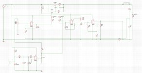
PSU schematic

Attached is the psu I simulated, the simulation is for a full analog model based around X2. The potentiometers Vr1 and Vr2(they are not necessarily optimal here lower values should be used) will get replaced with the dac from the microcontroller as well as R25 and R26 to match the DAC output voltage. The gain around X3 will also need to be adjusted to match the target current I want to achieve. Any feedback is welcome. psu schematics.JPG
I also had to remove some components to keep the bare bones due to the limitations in simetrix
 
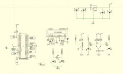
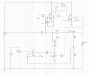
some update I have been able to get my code for rotary encoder user TIM4 and External interrupt for push button functions on a STM32VL discovery board, the same one I used when testing the analog part using ADC and DAC. Next step now is to assemble the code to have a digitally controlled PSU. I am looking at how Agilent implemented their power supply functionalities in the 363XX series its gives a good idea of how to proceed. In the meantime attached is the schematic of the 16F877A board and power supply I had used as prototype.A2.JPGA1.JPG
 
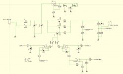
Another schematic on the bench

I have built the attached schematic PSU2.JPG and giving it a try. This one uses high side current sensing but the opamp used is temporary I am still thinking of whether to go with an ACS712 or MAX4080F. Any input is welcome. I have just received a STM32F103RBT6 board that can run at 72MHz I will see how things go.
 
I purchased some MCP4921 from ebay and got the PSU to work with a 16F877A , rotary encoder, LM324 and TIP output. The voltage is stable up to where my meter can measure i.e. up to 1mv precision. Voltage is stable and does not fluctutate and no oscillation present when changing voltage. Past all these tests I am now thinking what target to set for the PSU i.e. voltage current. I think I will start by building a very low powered one and decide afterwards. The 16F877A seems to have a tough time reading rotary encoder interrupts, sending SPI voltage to the MCP4921 and reading the ADC voltage. I might replace it with an STM32F103C8T6 and keep the RBT6 for some other application now that I have the MCP's
 
Top