My first attend on building smps

nikoskir

New member
Hello.
My name is Niko and i am from Greece.
I am following this forum for a while and i can say
that it is one of a kind regarding smps design and information.
So i decided after all the info I've collected to start building one.
My goal was to have an output of 13 volts 30 amps continuously.
I want to use it in hho production for oil burners ( i already use
Chinese power supplies which i am afraid are not able to work
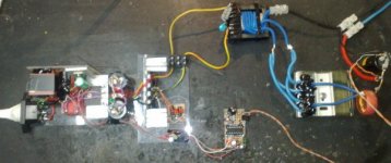
continuously). So here are some pictures of the project completely
made in bare-board just for testing. the design is based on a schematic
using sg3525 and ir2110 with some slight modifications.
I will post late at night schematic with modifications and more info about this project.
All i can say is that after 2 hours of working everything is stable with some heat
on mosfets , trafo and the output rectifiers. But i get sweat from the load bulbs as they produce a lot...LOL
thanks for reading.I forgot to mention that it is regulated through optocoupler.


1.jpg2.jpg3.jpg4.jpg5.jpg6.jpg7.jpg8.jpg9.jpg10.jpg11.jpg12.jpg14.jpg
 

Attachments

  • 0.jpg
    0.jpg
    35.2 KB · Views: 67
Last edited:

wally7856

New member
“I want to use it in hho production for oil burners”

hho = home heating oil?

What kind of oil are you making?

What does the 13V 30A power supply do?
 

Rthompson256

New member
Am I correct that you want to make hydrogen and oxygen out of water. From my experiments the power input is not worth what you get out.
 

nikoskir

New member
Hello ..

@wally:
I actually inject hho in air inlet of burners through a electrolysis process and after i reduce the fuel injector by 2 levels down even 3 in
some burners which have over 95% efficiency.So i build a system with hho cell and pwm which is producing 3 liters per minute at 30 amps.
The gain of this is around 30% reducing the overall cost (electricity plus oil).

@rthompson:
It is true that if you want to use the hho production alone for producing energy is not worthing , but if you use it to boost or better help
the fuels burn better with reduced emissions it is very good in results. Regarding the price of electricity and price of oil the overall result is
very efficient. Even in cars i have also good results. My car is a Golf 5 2.0L and i have 5.9 liters per 100 km for about 140 km per hour speed.
If the fuels were half the price as they are now, i wouldn't go to these projects.


Sorry for not posting the schematic yet.....i was to lazy last night. I try to do it during the day (Greece day :) ).

Take care
 

nikoskir

New member
So here is the modified schematic .
All mods came out of info i got here in diysmps.
For sure it is not the ultimate but i think it is ok in some level.
If you have any suggestions for the project please post them.
I will be very glad to see them.
I am not a guru but i am learning for sure.

modified sch.jpg
 

wally7856

New member
Are you sure you have a ETD59, that is a big core. Do you have a few dimensions i could check. I was going to run a few calculations.
 

nikoskir

New member
Are you sure you have a ETD59, that is a big core. Do you have a few dimensions i could check. I was going to run a few calculations.

Hello Wally...its not etd59.....i forgot to change in schematic..its an ee core similar dimensions to etd39 ( i have one and i compare)..you can see in picture..

thanks
i will fix the schematic..
 

nikoskir

New member
This is getting very hard to get the wire to fit. Do you have a chart of magnet wire sizes you can buy.

what do you mean fit?
are you trying to wind ?

the inner dimension of core is width=32 height=31 usable for winding.....
i don not have charts of wires......i used what i have.....actually the secondary is ~5mm or less outer dimension..the inner is about 3.6..
hope it helps
 

wally7856

New member
This is the way i see your transformer design.

Half bridge, so transformer will see 1/2 the voltage.
170vdc high
140vdc low

13vdc x 30A = 390W
390W x 1.3 for no PF circuit = 507W

507W / 140vdc = 3.62A

For continual use 500 cir mils per amp is a good design point.

3.62A x 500 cir mils = 1,810 Cir mils

1.1mm wire = 1.1481mm OD = 1,874Cmils = minimum wire size.

You need 30 amps out = large wire, that means running the transformer at a lower frequency. You can not go lower than 35khz because the EDT39 core will not be able to supply 507W with less frequency.

Max Gauss you can run at 35khz = 1800G

50khz, 1500G, Ae 1.249 = 45.4 turns = 46 turns / 2 for split primary = 23

You would split the primary for better coupling to the secondary. 23 + 23 turns.

You need 3 to 4 mm insulation on each side of the winding. You have 32mm of total winding area.

32 - 4mm -4mm = 24mm for wires.
32 - 3mm -3mm = 26mm for wires

26mm wire winding area / 23 turns = 1.130mm max wire size.

You need .1mm wire wire as a minimum size and it is a little to big to fit. And for the frequency it is a little big also for skin effect.

.1mm wire = 1.1481mm OD = 1,874Cmils = minimum wire size.
 

wally7856

New member
For the secondary.

N13 = 46pri x 14v / 140vdc = 4.6 = 5 turns.

30A needed with center tapped winding. Each winding has to supply 15A.

15A x 500 cir mils per A = 7,500 cir mils total for each secondary winding. This should be made up of multiple strands to reduce skin effect. 2 strands minimum, 3 strands better. All wires have to lay flat across the winding area, you can not twist them in a bundle.

2.24mm wire = 7,777 cir mils = 2.316mm OD

2 strands x 5 turns x 2 secondary’s = 20 total turns.

20 total turns. x 2.316mm OD = 46.2mm, ONLY ROOM FOR 26MM.

Now you have to go to 1 thick strand, very poor for skin effect.

2 secondary's 5 turns each = 10 turns total.

26mm winding room / 10 turns = 2.6mm max dia of wire.

2.5mm wire = 9,687 cir mils = 2.5780mm OD, This will fill winding area and have extra cir mils. But very poor skin effect.
 

nikoskir

New member
Hello wally..

thanks for all this info..i know it took some of your time to do calculations.
I know that if you use thick wire as the frequency goes higher the current will flow in less area of wire pointing to outer
surface...
so multi wiring is best..
My first attempt was very simple in thinking.
i took this schematic and only changed the secondary windings and did my tests..which they were very good for me as a start.
As for the power dissipation you wrote that it needs 507w input for 390w output.
correct if i am wrong...but as i did my tests in my design it is far away from that.
if you look at the pictures you will see measurements in real time.
The only measurement is missing is the secondary current which i know it is 30 amps at 13 volts(measured with simple power supply with amp meter on it).
Maybe i measure the wrong way..but for every 10 amps the input ac current is about 0.65 amps at 220v (i use isolated trafo 1000w) .
As for your calculations i need etd-49 and higher for this to work properly.
Actually i am waiting for an order i made for trafos many kinds but they need time to arrive in Greece.
So i cannot do any test for now...
I was thinking of using 2 of these trafos with secondary 7 volts working in series the secondaries and see the results. i do not want to use 2 trafos 13v in parallel
because even if i wind them perfectly they will not be the same....so in series i will have the same current flowing ...correct if i am wrong..

thanks in advance

Niko.
 

wally7856

New member
“As for the power dissipation you wrote that it needs 507w input for 390w output.
correct if i am wrong...but as i did my tests in my design it is far away from that.
if you look at the pictures you will see measurements in real time.
The only measurement is missing is the secondary current which i know it is 30 amps at 13 volts(measured with simple power supply with amp meter on it).
Maybe i measure the wrong way..but for every 10 amps the input ac current is about 0.65 amps at 220v (i use isolated trafo 1000w) ."

I used 1.3 x 390W because in several publications i see a number of 25 to 30% used for worst case on a half bridge. Your numbers seem to show only 10%. I do not see anything wrong with your measurement’s and can not explain the difference.


“As for your calculations i need etd-49 and higher for this to work properly."

That is what i was thinking also.


“I was thinking of using 2 of these trafos with secondary 7 volts working in series the secondaries and see the results. i do not want to use 2 trafos 13v in parallel
because even if i wind them perfectly they will not be the same....so in series i will have the same current flowing”

I think you are correct. Series is better for the secondary.


Wally
 

wally7856

New member
A few suggestions for your power supply.

1) Use split primary. From above calculations wind as 23 turn primary - 5 turn secondary - 23 turn primary.

2) Use more input capacitor. A general rule of thumb is 3uF per watt. With your measured 430W x 3uF = 1,290uF

Remember that capacitors in half bridge are in series so you only get 1/2 the value.
1290uF x 2 = 2,580uF

So as a minimum use 2 pcs of 2700uF or 3300uF rated 200vdc or more. And do not forget to add some high frequency caps across the electrolytic’s 1uF or so.

3) I see you are using 12vdc to power the IR2110. You might get by, but 15vdc would be safer. The 12vdc tends to drop a little at the end of a cycle.

4) Depending on how tight you need voltage regulation, use a TL431 to make a regulator for your opto-coupler. But for electrolysis it probably does not matter.

But all in all you did very well. Your first SMPS gave you what you wanted 13vdc at 30A.

Wally
 

nikoskir

New member
A few suggestions for your power supply.

1) Use split primary. From above calculations wind as 23 turn primary - 5 turn secondary - 23 turn primary.

2) Use more input capacitor. A general rule of thumb is 3uF per watt. With your measured 430W x 3uF = 1,290uF

Remember that capacitors in half bridge are in series so you only get 1/2 the value.
1290uF x 2 = 2,580uF

So as a minimum use 2 pcs of 2700uF or 3300uF rated 200vdc or more. And do not forget to add some high frequency caps across the electrolytic’s 1uF or so.

3) I see you are using 12vdc to power the IR2110. You might get by, but 15vdc would be safer. The 12vdc tends to drop a little at the end of a cycle.

4) Depending on how tight you need voltage regulation, use a TL431 to make a regulator for your opto-coupler. But for electrolysis it probably does not matter.

But all in all you did very well. Your first SMPS gave you what you wanted 13vdc at 30A.

Wally

Hello Wally...
i really admire you of being so interest in my project..
as for ir2110 if you look at the schematic i took unregulated supply before 7812...the original one you are right had both ic at 12v.....
as i told you i read a lot and i keep in use all useful info and tips about things working...
as for capacitors i only had these for now.....but for sure i will go for more........

as for 1uf high frequency caps do you recommend any specific one.....and please tell me why do i have to use them.......what is the theory of them...

thanks in advance

Niko
 

wally7856

New member
“i really admire you of being so interest in my project.."

We all like to save energy!!!


“as for ir2110 if you look at the schematic i took unregulated supply before 7812...the original one you are right had both ic at 12v....."

OK i missed that, good work.


“as for 1uf high frequency caps do you recommend any specific one.....and please tell me why do i have to use them.......what is the theory of them...”

Electrolytic’s both input and output, slowly burn up with high frequency switching noise on them. Ceramic caps have good high frequency behavior, 1 or 2uF caps would help a lot across each electrolytic. Ceramics are best used for output section were voltage is low, or price goes way up. You have to look thru other capacitor types to find less expensive 200vdc cap.

If this link works in the application window it will say SMPS.

http://www.digikey.com/scripts/dkse...cts=0&ptm=0&fid=0&quantity=0&PV13=253&stock=1
 

nikoskir

New member
tomorrow i will try the 2 trafo and also the tl431 implementation as you mentioned ...
i will post my results....
So another option is to use current mode regulation...
and why is that? i will explain..
Hho cells when they start to heat up current is rising dramatically with very bad
results as for lot of current and as for bad production(not pure mixture)
till now i am using a pwm in push pull mode which also has current regulation in 13volts.
its my design and it is accurate 5% at regulation from 90% till down to 5% of pulse width.
I use this method because the most common cells are with 11 plates which are center taped connected(1minus-4neutral-1plus-4neutral-1minus).
Most of pwm are connecting together the minus into one and the center to plus voltage.
As you can see the center plate is getting twice as fast the temperature high and also shares double current.....
with push pull topology its much better with results and the cell works flawless.
An hho cell when it is cold and lets say we use mixture which draws 10 amps straight..at the temperature
of 70 degrees celsius inside the cell it rises up 3 times!!!!!
so if we need steady production from cold to up heat we have to adjust the mixture at least 1.5 times upper.
the pwm as you can understand is getting very stretched at high temperatures of the cell also the smps
because it is stretched with high current low pulse width(as temp goes up pulse is going down) at 150hz frequency.
For sure pulse will be on the cell (pure dc is not working because when a bubble is generated is stays stacked on plate longer)
but with current regulation in both sides will help pulse width of pwm to work at 70%.....which is perfect for production....

i don't know if i made my thoughts clear...if not please ask me i will be glad to answer or explain..

Niko
 

nikoskir

New member
“i really admire you of being so interest in my project.."

We all like to save energy!!!


“as for ir2110 if you look at the schematic i took unregulated supply before 7812...the original one you are right had both ic at 12v....."

OK i missed that, good work.


“as for 1uf high frequency caps do you recommend any specific one.....and please tell me why do i have to use them.......what is the theory of them...”

Electrolytic’s both input and output, slowly burn up with high frequency switching noise on them. Ceramic caps have good high frequency behavior, 1 or 2uF caps would help a lot across each electrolytic. Ceramics are best used for output section were voltage is low, or price goes way up. You have to look thru other capacitor types to find less expensive 200vdc cap.

If this link works in the application window it will say SMPS.

http://www.digikey.com/scripts/dkse...cts=0&ptm=0&fid=0&quantity=0&PV13=253&stock=1

thanks i will check it.....
 

nikoskir

New member
A small update..
the implementation of tl431 was very good indeed
it works much better..
also the noise comes from trafo when there is no load
is much much lower...
i don't know if there is a way to reduce more that noise...

as for current regulation i am thinking of using a copper wire at the output
of regulated 13 vdc through a comparator with proper calculations and together
with my pwm's comparator to get what i want 70% pulse width at output on cell.
what i mean is if my cell needs 20 amps the smps will regulate current at ~25 amps
so my pwm can produce pulses to the cell..

i think i am clear..or not??

thanks

take care
 
Top