My ucd car amplifier

Ferda

New member
Hi all,

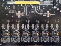
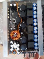
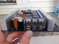
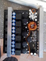
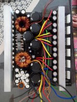
This is my first post here. I could not find time to post for a long time. Anyway, people probably know who i am and they know the circuit from other forums. It was very long time ago to start this design and project. But due to the my profession i could not find some time to finish it. The photos below belong to the nearly finished amp. It gives 186W RMS into 4R speaker. And as you can see it is a six channel class-d car amp oscillating at ~400Khz.

Best wishes,
Ferda
 

Attachments

  • 1.jpg
    1.jpg
    408.2 KB · Views: 320
  • 4.jpg
    4.jpg
    248.6 KB · Views: 260
  • 3.jpg
    3.jpg
    167.4 KB · Views: 233
  • 2.jpg
    2.jpg
    220.9 KB · Views: 195
  • 100_3699.jpg
    100_3699.jpg
    274.9 KB · Views: 245

ultra

Member
Congratulations !

Excellent work !

Could you please write a few things about the smps? (Fosc, etc)
 

kanon

Member
I think you copy photos from diyaudio not think it's their job ... because nick change .. nothing personal
 

Ferda

New member
Ofcourse, The smps is unregulated and the osc frequency is 75kHz. So the actual switching frequency is 37.5kHz. The mosfets for smps are IRF3205 driven by 5240/4240 bipolar totem pole BISS transistors. There are 8 mosfets. The output rectifiers are F20C12/F20A12 and the output voltage ±39V on idle with 12.5V Vin.

Congratulations !

Excellent work !

Could you please write a few things about the smps? (Fosc, etc)
 

Ferda

New member
I think you copy photos from diyaudio not think it's their job ... because nick change .. nothing personal

Really, then go on there. It is belong to me. Search diyaudio with my nick 'Whortless' and you will see my name at the bottom of some posts. I do not have time to express myself to you.
 

Ferda

New member
Hi
can you please share your class d amp shematic?

Actually i do not have time to draw all the schematic. You can use Bender.ru's schematic to create the amp. Mine is a bit different there are passive poles on the input/feed back path as the inventor Bruno Putzeys' described on the orginal UCD paper.
 

Ferda

New member
Read about irs2092 , iraudamp7D & iraudamp7s .

It's a great chip and friendly to use it.

Dear pipiripao,
Many thanks for your advice. I do not want to use delta/sigma pre-feedback topology. I like the control topology of UCD. However, there are no so much info in the literature about it, except the Bruno's. Anyway, I know the irs2092 and some newer multi channel driver ICs from IR. Thanks
 
Last edited:

Ferda

New member
wow nice work freda . what voltage are you using and what are your output fets?

Thanks,
The output mosfets of the amps IRFB5615 and the supply voltage ±39V with unregulated smps and 12.5V Vin. The output inductor, i wonder you will ask, is 1D23A-330M from ice components (samples).
BW

BTW: my name is FERDA not FreDA :).
 

kanon

Member
Ofcourse, The smps is unregulated and the osc frequency is 75kHz. So the actual switching frequency is 37.5kHz. The mosfets for smps are IRF3205 driven by 5240/4240 bipolar totem pole BISS transistors. There are 8 mosfets. The output rectifiers are F20C12/F20A12 and the output voltage ±39V on idle with 12.5V Vin.


ohhh..! please came on..
 

ultra

Member
Ofcourse, The smps is unregulated and the osc frequency is 75kHz. So the actual switching frequency is 37.5kHz. The mosfets for smps are IRF3205 driven by 5240/4240 bipolar totem pole BISS transistors. There are 8 mosfets. The output rectifiers are F20C12/F20A12 and the output voltage ±39V on idle with 12.5V Vin.

Very good Ferda. Your pcb looks just fine.
Do you use the mains common mode chokes to the secondary of your trafos to eliminate switching noise?
How many amperes per square millimeter do you calculate on your trafos?
In my opinion, the Fosc is too low to get all this power output.
Personally i have designed a car class AB power amplifier, but the Fosc of the pwm is very high.
Whenever i have some time, i will start a thread.
Again, good job!
 

Ferda

New member
Very good Ferda. Your pcb looks just fine.
Do you use the mains common mode chokes to the secondary of your trafos to eliminate switching noise?
How many amperes per square millimeter do you calculate on your trafos?
In my opinion, the Fosc is too low to get all this power output.
Personally i have designed a car class AB power amplifier, but the Fosc of the pwm is very high.
Whenever i have some time, i will start a thread.
Again, good job!

Hi Ultra,

Thanks for your comments.
The output inductors of secondary side removed from old PC power supply and right they are mains common mode chokes, but they are re-wound with higher current capacity and required value.
I can not remember the current density of pri. or Sec. now. But the primary side 6*1.05mm and secondary 4*0.8mm on each winding.
The transformer cores from magnetics and they are P materials TC38613. If one have a look to their power capacity they are enough for this purpose.
The switching frequency selected 1/10th of amps' switching frequency but can easily be changed a bit upper.
I have ordered the PCB from a china manufacturer as i implied in diyaudio and it was a pain.

BW
Ferda
 
Top