Hi All
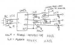
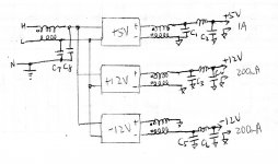
This is my first post here. I design my own hifi power amp and I want to use switching power supplies for +/-12V and +5V. Attached is the rough schematic. I wrote the current requirement of each supply which is 1A, 0.2A and 0.2A for +5, +12 and -12 resp. I am using 3 individual supply, I cannot find a triple supply that is thin enough to fit into the amp as space are very tight ( really too bad, I only have 1.2" gap, most are 1.4" or so thick). I am buying these on ebay from China, there is no spec with frequency they are running. These are what I am going to order:
https://www.ebay.com/itm/10W-5V-Ultra-thin-Single-Output-Switching-power-supply-for-LED-Strip-light/261849308076?ssPageName=STRK%3AMEBIDX%3AIT&_trksid=p2055119.m1438.l2649
https://www.ebay.com/itm/10W-12V-1A-Ultra-thin-Single-Output-Switching-power-supply-for-LED-Strip-light/261984664098?ssPageName=STRK%3AMEBIDX%3AIT&_trksid=p2055119.m1438.l2649
I assume the frequency is about 50KHz.
Also, I need to get one for the AC input also.
Please advice what value I need to buy. Also, what range of values for those caps.
Thanks
Alan
Attachments
-
 Schematic.jpg163.2 KB · Views: 19
Last edited: