Need help for opto driver

mihaiu16

New member
Hello everyone,
I'm new in this domain and I want to make a smps with optocoupler driver. i need your support for this project.
In the past I built some smps, but with transformer driver ( GTD ) and also I tryed the IC IR2110 ( and I couldn't made this to work...every time when I used this driver the IC and transistors burned.)

Here is the scheme which I'm based (for the upper transistor) and for the lower one it's more easy.
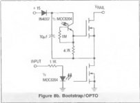
kVEJO.jpg


Before driver I will use PWM oscillator SG3525 without regulation for output voltage. I want to make an audio power supply and I don't need regulation, What I want it's an simple and robust design.
The main transformer will be an ETD 49 wich it's made for an switching frecwenci of 70kHz and 62Vcc.
I used for bobinating of the primar winding an number of 4 wires with a diameter of 0.6mm and for secoundary, two simetrical bobins made with 6 wires and the same diameter.
 

Silvio

Well-known member
You can follow the tread of LUDO 3232 for the 1000w smps using an ETD49 transformer. You can find everything you need including the pcb in pdf and also gerber files. This smps uses sg3525 and IR2110.
As for myself I never had any issues using IR2110 and SG3525 chips. It is the way you have to advance gradually while testing the smps. An oscilloscope is a must in this kind of work as without it you will never know what is happening.
A good transformer design is one of the keys for a good smps. Signal paths are to be kept away from high current paths and kept short as possible. If you decide to design your own pcb then a pin header which will carry the oscillator chip and driver will help to keep sensitive signal paths short and away from high current paths.
I also have my own design for a 1000w smps and this can also be found here. I built this smps with what I had available and some parts may not be available to you.

You can find the tread here https://www.diysmps.com/forums/showthread.php?872-1000w-smps-based-on-LUDO3232/page46

You can find the youtube video here https://www.youtube.com/watch?v=18l-plvqkdU&t=1s

You can find a tutorial for winding small transformer for smps here https://www.youtube.com/watch?v=_K3ixhcTYFg&t=1s

If you need anything else let me know

Regards Silvio
 

mihaiu16

New member
Hi Silvio!
I know all the tread I looked with interest and I read the discussion and advice that you, microsim or ludo gave. There it's very precios information and I'm glade that all the peoples are so good and give so many explanations in this domain not so accesible.
I have an analogical osciloscop, HAMEG HM1005 whic it's all that I need (100MHz 2 chanels).
What I want it's to try this type of driver.
I worked wit ir2110 but now I want something new, the only thing that I don't have now are knowledge about this type of driver.
I know a little about but I'm not feel ready to test and also I don't want to waste time with many testes.
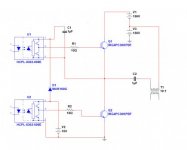
Here I made an principle scheme.
On this I need help what do you think, it's ok? opto drive sch.jpg
 

Silvio

Well-known member
@ mihaiu16

I have seen the datasheets of the opto drivers and transistors. The output current of the optocouplers are a little bit on the low side compared to the IR2110 one being of a maximum of 400mA while the IR2110 is 2A. The opto driver is meant to drive small and medium sized devices. One should also note that this is very critical as if you intend to drive larger devices there will not be enough gate current to switch the transistor in time. By checking the datasheet of the IGBTs used in your case well I think using the HCPL-032 opto driver may be enough. It is best to calculate the switching time with the current available on the gate driver to see if it switches in time according to the frequency and gate charge needed for the transistor being used.

I am posting a PDF file to help you work out the gate resistor and also to calculate the switching time.

View attachment Calculation of snubber components and driver gate resistors.pdf

Regards Silvio
 

MicrosiM

Administrator
Staff member
IR2110 is a robust chip if used properly with the proper PCB layout, and can easily drive 4 IGBTs without any issues.

Using those optos also is a robust solution, but you need to make proper design, use the correct didoes at the + rail for the opto, use some schottky, zeners, etc..

and very important PCB layout, otherwise you will have nast oscillation with those OPTOs if you miss any part from the above.

Good luck!


You may take a look at my test here, with SMPS with PFC under development with OPTOs, but different ones for sure

[video=youtube;_sbvyMyv3Qs]https://www.youtube.com/watch?v=_sbvyMyv3Qs[/video]
 
Last edited:
Top