new project, AC/DC TIG welder

fobar22

New member
Hello everyone, since this is my first post on the forum I will give a little background information on myself. I have a degree in Mechanical Engineering, which means I know just enough about Electrical Engineering to get myself into trouble. And I am a tool addict with many projects ranging from completely restoring my 1965 Ford F100, to building a small PID controller for my smoker to control airflow. My garage is coming along, but one thing I don't have is a TIG welder, and I have always had an interest in building my own. And unfortunately I have all the time in the world on the computer, but have no access to any tools or the ability to build test circuits for the time being.

Now I don't plan on just jumping into building a huge SMPS as my first project, I do plan on experimenting with smaller ones, I figured that would be best for my health, and my pocketbook.

Now I have been reading a lot of material in regards to SMPS's and working on a design in building blocks, but I keep bashing my head trying to understand transformer design. With a TIG welder basically being a large constant current power supply, and my understanding so far, I plan on working on a full-bridge topology working at 100MHz that is fed through a single rail center tapped transformer. The output ratings should be in the range of 225A @ 29V, with a minimum current of 5A (these are based off Miller's dynasty250).

So far I plan on using IXYS IXFH60N50P3 for the primary switching, GeneSiC MBRT400100 to rectify the voltage on the secondary side, and then building an air core inductor using 1/0 welding cable. I am still working on the parts list and I hope to keep learning on this forum.

My biggest question right now is about the transformer, I feel like the size doesn't make sense, but then again my experience is very limited. So am I on the right track:

ETD 59/31/22/N87, 26x26AWG@15 turns each on the primary, and 48x20AWG@2+2 turns on the secondary.

Thanks for any help, hopefully I will be able to work on this project through completion with your guy's help.

Dave
 

wally7856

New member
Dave, I like your project. It is something i have thought about trying to do. I have been studying SMPS power supplies for about 3 years now and i do not think i am ready to take on anything this hard/complex yet.

Be prepared to spend thousands of dollars for parts and equipment to design this. Oscilloscope, isolation transformer, amps, volt, temp - meters. Wire of all kinds, litz, copper foil. And more burned out FET’s than you can count.

Another aspect of this project is high frequency start. Other than knowing it exists i do not know anything about it. What frequency, what voltage is it, what current, how do you inject it?

“My biggest question right now is about the transformer, I feel like the size doesn't make sense, but then again my experience is very limited. So am I on the right track:”

That ETD 59 is probably 4x to small, in my opinion. Theoretically it is good for 8,200W, but practically you can not get enough copper in it to wind for that wattage.

Here is a recent thread from someone who took a 3 in 1 welder apart.

http://www.diysmps.com/forums/showthread.php?248-400A-16V-Regulated-Power-Supply
 

Kanwar

Member
Dave,

Your switching frequency as per you is 100MHz, is that for real? I can't think those mosfets can switch that fast.
 

noz-25

LEDadict
Zika

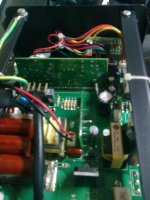
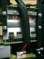
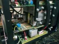
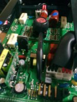
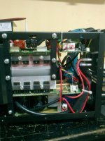
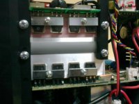
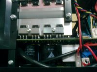
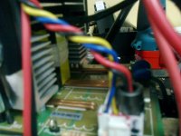
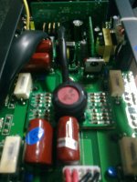
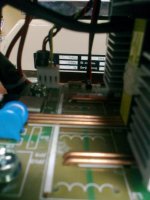
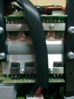
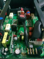
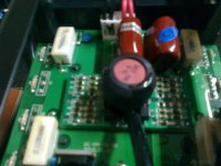
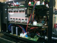
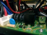
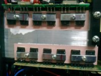
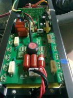
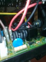
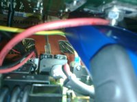
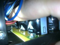
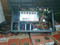
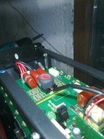
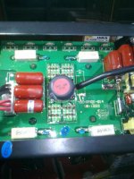
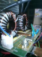
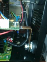
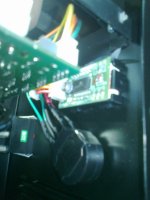
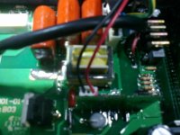
Hello Dave!I will show You some pics and video of "Zika" welding maschine,new models.I am immpress with quality of PCB and everything others.They are sooooo goood.Smaler one is Zika mini and it's 160Amps.Stronger one is 200Amps.I try it both and they POWER for REAL!Just look at those MOSFETS,system of cooling...Model with 200Amps has 24 MOSFET-s!Core is not to big but i don't know wich is excatly.Frequency is for both model 120KHz and duty cycle 60%.Enjoy:
[video=youtube;evvwZDXlFqA]http://www.youtube.com/watch?v=evvwZDXlFqA[/video]
[video=youtube;MsbQKr50_JU]http://www.youtube.com/watch?v=MsbQKr50_JU[/video]
[video=youtube;rzAmJA9jjJY]http://www.youtube.com/watch?v=rzAmJA9jjJY[/video]
Fotografija0252.jpgFotografija0234.jpgFotografija0235.jpgFotografija0236.jpgFotografija0237.jpgFotografija0238.jpgFotografija0239.jpgFotografija0240.jpgFotografija0241.jpgFotografija0242.jpgFotografija0243.jpgFotografija0244.jpgFotografija0245.jpgFotografija0246.jpgFotografija0247.jpgFotografija0248.jpgFotografija0249.jpgFotografija0250.jpgFotografija0251.jpg
 

fobar22

New member
Opps, sorry for the typo, I meant 100kHz, if I was building that fast I would probably be making a lot more money for myself than I currently am....

Thanks for all of those pictures, I have been having a hard time finding pictures inside welders to get an idea of what is going on. After looking at all of them, and comparing them to the Zika website, I think those are the 160A and 200A stick welders. While stick can be used as a TIG, they are not exactly the same since TIG will include constant current adjustment by foot pedal or hand wheel, also a TIG would include a gas control solenoid. I mention this only because it helps to realize what is being looked at in all of the pictures.

I am only going to reference the larger of the two machines, Obviously the tank/input capacitors are on the bottom, I am guessing the rectifier is somewhere on that board as well. I still haven't figured out why there are three different colored wires leaving the power input board (red, black, and blue). I feel like the switching portion of this inverter is the top board, it doesn't seem like the bottom board has the gate control circuit to support a parallel bridge with the top. Also you can't see the all important diodes following the transformer, which leads me to believe that the bottom 8 "mosfets" are actually some kind of sckottky diode (maybe 60APU02PBF). From a manufacturing stand point it would be cheaper to use a package like that.

All of this leads me to believe that they are using a full-bridge topology for both welders, the smaller one using 2 power mosfets on both the high and low sides, and then 3 for the larger one. Again from a manufacturing stand point they would be building modularity across their line. I wouldn't surprise me that if you opened up their true TIG welders, you would see a very similar design.

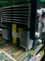
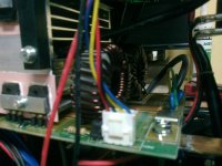
The transformer itself is tucked inside the heat sink, probably to aid in convection cooling, and then the double toroid inductors must be the output chokes in parallel to support such high current. Which by reference to the surrounding parts, the size of the transformer starts to give me reference to what is necessary to support such high power.

Now I do have to say their heat sinking is very impressive! Its got to be to take away all of that heat! Of course that is just one of the many design challenges that make projects like this interesting.

Dave
 
Last edited:

noz-25

LEDadict
Dave
I am going now (it's 06:30 AM) on the job.I will try the find answers for Your question about rectifier,mosfet....Will post new pictures again,for 8h starts now.
Regards!
 

noz-25

LEDadict
Opps, sorry for the typo, I meant 100kHz, if I was building that fast I would probably be making a lot more money for myself than I currently am....

Thanks for all of those pictures, I have been having a hard time finding pictures inside welders to get an idea of what is going on. After looking at all of them, and comparing them to the Zika website, I think those are the 160A and 200A stick welders. While stick can be used as a TIG, they are not exactly the same since TIG will include constant current adjustment by foot pedal or hand wheel, also a TIG would include a gas control solenoid. I mention this only because it helps to realize what is being looked at in all of the pictures.

I am only going to reference the larger of the two machines, Obviously the tank/input capacitors are on the bottom, I am guessing the rectifier is somewhere on that board as well. I still haven't figured out why there are three different colored wires leaving the power input board (red, black, and blue). I feel like the switching portion of this inverter is the top board, it doesn't seem like the bottom board has the gate control circuit to support a parallel bridge with the top. Also you can't see the all important diodes following the transformer, which leads me to believe that the bottom 8 "mosfets" are actually some kind of sckottky diode (maybe 60APU02PBF). From a manufacturing stand point it would be cheaper to use a package like that.

All of this leads me to believe that they are using a full-bridge topology for both welders, the smaller one using 2 power mosfets on both the high and low sides, and then 3 for the larger one. Again from a manufacturing stand point they would be building modularity across their line. I wouldn't surprise me that if you opened up their true TIG welders, you would see a very similar design.

The transformer itself is tucked inside the heat sink, probably to aid in convection cooling, and then the double toroid inductors must be the output chokes in parallel to support such high current. Which by reference to the surrounding parts, the size of the transformer starts to give me reference to what is necessary to support such high power.

Now I do have to say their heat sinking is very impressive! Its got to be to take away all of that heat! Of course that is just one of the many design challenges that make projects like this interesting.

Dave
You are right.It's not all MOSFET-s!See Your self an pics.One more think:there is 3 Transformer inside heatsink!Very immpresive electronic.Here is more video and pics!Enjoy!
[video=youtube;XWOepQ9Jdc4]http://www.youtube.com/watch?v=XWOepQ9Jdc4[/video]
[video=youtube;EVGGQMXxoWE]http://www.youtube.com/watch?v=EVGGQMXxoWE[/video]
[video=youtube;jZnq8sAr1IQ]http://www.youtube.com/watch?v=jZnq8sAr1IQ[/video]
[video=youtube;7PebB27ryaE]http://www.youtube.com/watch?v=7PebB27ryaE[/video]
Fotografija0272.jpgFotografija0273.jpgFotografija0274.jpgFotografija0275.jpgFotografija0277.jpgFotografija0278.jpgFotografija0279.jpgFotografija0280.jpgFotografija0281.jpgFotografija0282.jpgFotografija0283.jpgFotografija0284.jpgFotografija0285.jpg
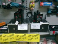
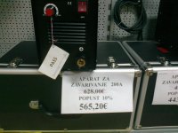
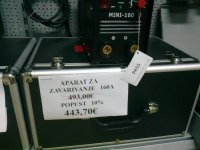
I post pics of their prices in my store.As You can see they are realy expensive!
 
Last edited:

fobar22

New member
parallel transformers

Wow, 3 transformers.
Well that begs the question, how do they have them in parallel? Or at least how would one do that?

I can think of a few ideas, but what is the best way to have multiple h-bridges and multiple transformers in parallel, but still operating off one controller for a full-bridge topology.

Use one controller and have all the mosfet gates being driven by that, then would you have the mosfets feed into one main line that is then split again feeding into the transformers, or would you have one h-bridge of mosfets for each transformer keeping the lines separate.

And then following the transformers, do you have them feed into each of their own rectifier bridges, or join together before feeding into one large rectifier bridge.

I can see how making the wrong choice, or using poorly matched parts can cause problems. So I am curious how this gets done properly.
 

noz-25

LEDadict
View attachment Welding maschine aap note.pdf
Wow, 3 transformers.
Well that begs the question, how do they have them in parallel? Or at least how would one do that?

I can think of a few ideas, but what is the best way to have multiple h-bridges and multiple transformers in parallel, but still operating off one controller for a full-bridge topology.

Use one controller and have all the mosfet gates being driven by that, then would you have the mosfets feed into one main line that is then split again feeding into the transformers, or would you have one h-bridge of mosfets for each transformer keeping the lines separate.

And then following the transformers, do you have them feed into each of their own rectifier bridges, or join together before feeding into one large rectifier bridge.

I can see how making the wrong choice, or using poorly matched parts can cause problems. So I am curious how this gets done properly.
Dave
I found this one App note,it's exactly what You are looking for.I know i have some where and better one complete project.You must be aware it's not simple task.Here is this one for now,but i will find and another ,better one.
Regards,Nikola
 

wally7856

New member
I have looked at that AP note many times trying to figure it out. What i do not understand is on page 14 the output section. One side of the transformer secondary goes to a single dual diode package and the other side goes to two dual diode packages. All dual diodes are STPS61170CW, I forward 2x30A. The output is 135A, how can this work? 2x30A = 60A. And how can one diode pack be enough on one side of the secondary winding and two packs needed on the other side of the secondary winding.

I do not think it is a mistake on the schematic because these three diode packs are talked about on the bottom of page 12.

Does anyone understand what is going on?
 

noz-25

LEDadict
I have looked at that AP note many times trying to figure it out. What i do not understand is on page 14 the output section. One side of the transformer secondary goes to a single dual diode package and the other side goes to two dual diode packages. All dual diodes are STPS61170CW, I forward 2x30A. The output is 135A, how can this work? 2x30A = 60A. And how can one diode pack be enough on one side of the secondary winding and two packs needed on the other side of the secondary winding.

I do not think it is a mistake on the schematic because these three diode packs are talked about on the bottom of page 12.

Does anyone understand what is going on?
You are not read very good datasheet.RMS forward current is 80A per diode.
 

fobar22

New member
Regardless on the diodes' rating, I surely don't understand why there are two on one leg, and only one on the either. But as I originally said, I'm extremely limited on my knowledge, that's why I am here in the first place.

So, I have been doing lots of reading, and I think I am working out my plan of attack on this project. As of right now I am working on my microcontroller programming skills, getting more familiar with the Arduino family of products. I have worked only with PIC in the past, and I'm trying to broaden my knowledge. So far I have learned that Arduino makes building the circuits and writing the code simple, but at the cost of sever restrictions once you really get into it, mostly on the hardware side since you can still use the AVR libraries in the Arduino IDE.

But all the same, I plan on becoming very familiar with reading analog sensors, transmitting data over serial connections, and controlling PWMs. In the end I plan on having a wireless control (much like Miller offers) to change settings without moving to the welder itself (more of a convenience thing, it will probably be the very last piece of the puzzle.) A wireless arc control pedal, anyone familiar with TIG already knows, the pedal will let the welder start the flow of shielding gas, and then start the welding arc. Once started the pedal allows the welder to adjust the "heat" of the arc, the SMPS's current output. Now having the sweet wireless pedal really only takes one cable off the floor to trip over, but I figured that two 2.4GHz transceivers ($50 max from SparkFun), and some time working on the code would be cheaper and easier than running multiple wires to a pedal, and then putting some kind of loom on it to protect from the abusive garage environment. Now this all assumes that the RF energy from the welder doesn't mess with the 2.4GHz transmissions. If it does, I will just find a different use for the transceivers and then make the pedal with some microphone cable. So until I get back to my shop, I have some kind of work that I can do.

Once I do get back in a few months, I think my first step will be to make the DC->AC square wave circuit. I have looked at a few different options in terms of IGBT's. The max frequency of this portion will be 300Hz, so really the IGBT's just need to be able to handle the current, and switching speed shouldn't be too important. I have read that I can either parallel multiple IGBT's (using 12 or 16) to make the H-Bridge. Or I can use 4 IGBT Modules that are able to handle much higher current, but come at a steep price tag, of course I have found a set of 4 on Ebay for $100... Used though, it would be a gamble on their functioning.

The reason that I think I will start with the DC->AC is because I already have a "buzz box" stick welder that is capable of DC output. I have no idea how clean of a source it is, but I can put a few capacitors between the large (very LARGE actually) transformer/rectifiers of the buzz box, and my DC->AC circuit to clean up the power. I will need these capacitors in the end anyways, to clean up the 220VAC from the wall.

If I pass this gate of making the DC->AC portion, I then will tackle the HF/HV arc start portion, either using a neon sign transformer of automotive ignition coils to generate the high voltage. I am still vague on this portion. But I do know that a sparkgap is used, I am under the understanding that the sparkgap and capacitor circuit cause the HF. And then to couple the HF/HV to the welder output I will do something like this guy,

http://www3.telus.net/public/a5a26316/TIG_Welder.html

Look at the 6th picture, you can see the white high voltage line coiling around the larger black coil to couple the two.

Dave
 

wally7856

New member
My conclusion of the number of diodes on each leg is it has to be a mistake.

As for your plan, i think it is very realistic. Using your existing stick welder for power supply is zero cost and you know it works. The bridge for 300hz operation can be made cheaply with lower current FETS or igbt’s. To prove out the circuit just use components rated for a few amps. When you have it working move up in current and try again.

Here is a thread about making a tig welder. It never really came up with a working tig welder but there was a lot of discussion about high frequency power sources. Most of the high freq stuff was one of a kind or not reproducible but one or two designs were usable. The usable stuff was roughly in the middle of the thread.

http://www.cnczone.com/forums/welding_brazing_soldering_sealing/21978-my_homemade_tig_welder.html
 

tebci

New member
@fobar22

have you finished any SMPS projects related to this one?

I am also looking to build welder, please share your schematic if you can


thanks
 
Top