PGA2311 Digitally controlled pre-amp

I am about to embark on a project using microchip controller and PGA2311 as a pre-amp. Am waiting for these to arrive: PGA2311 ic, HD44780 LCD, Rotary encoders, some 16F628 A to start playing with and mess around with things and some 16F877 soon to be purchased. Still deciding about Hi-tech C or assembly . I'll be using MPLAB IDE to program the microcontrollers and a pickit3 clone programmer.

Am not planning to have plenty of inputs to spare the need for additional ic's that will control relays serially.

If anybody wants to share anything you are welcome. I'll be starting as the pic arrive to build a simple power on/off and input select with leds as status display.

Then the LCD and last the PGA2311 and rotary encoders
 
Very Nice.

I am planing the same project here, but using 4 PGA´s for a 7.1 set. I am planing to use PIC too.

For now I am staring working on the IR reception for another project (stereo 4 input selector with motorized volume control)

Sure we can share some information.

Mauricio
 
Hi Mauricio thanks for your reply great we can share info. I just got my 16F628A am waiting for some more parts to get in. I need to buy some leds and tact switch this weekend and get started with the project. Are you planning to use C or assembly? Am also planning to extend this setup to a 5.1 or 7.1 project. The only resources i found on the net relating to this kind of project are the following:
Stereo unit:http://www.mhennessy.f9.co.uk/preamp/index.htm
7.1 unit:http://www.electro-dan.co.uk/preamp/construction.html

Speaking of IR i made a small project begining this year but it did not turn out right I wanted to send IR remote over FM(we still have some non crowded region in FM band here). The fm transmitter worked but i did something wrong interfacing the IR receiver amp to the transmitter think i lost the carrier on the way. the circuit consisted of a BF245 Jfet buffer, this FM transmitter tuned to 100Mhz: http://www.sound.westhost.com/project54.htm. I got signal reception up to 10 metres with signal going through walls when sending music through the transmitter but IR signal recovery with FM receiver was very very bad. I've put it aside maybe i will come back to it another time. Do you mind sharing your schematic or by mail?

Thanks
 
Last edited:
I have started playing with the pic i am using a 16F84A with 4MHz crystal and hi tech c Lite in MPLab IDE. After some test and checking switch debounce time with oscope. I managed to build the power on/off part which is the main program section. I will be diving on making an input selector soon with that 16F84A. My HD44780 and rotary encoders are still on their way to my place. How are things going on your side?
 
In my case, it´s going slow, I had been working a lot in my job and did not have enougth time to work on the project.

Hope I can resume the work on the next weekend.

Mauricio
 

Yosemite

New member
dear zeus_-threat


You are doing very well, i hope to see your projects completed, because I want to build them ;)
 
Current Test schematic and more

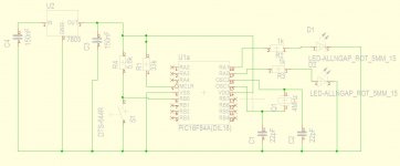
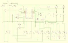
This is the currenttest setup Schem.JPG i will move switches to PortA and keep PortB to switch sources. That means 1 power switch on RA0, 1 on RA1 for moving down the input source selection 1 switch on RA2 for moving up source selection. That will make for a total of 8 sources which can be switched using relays or anything else. This is indicated as leds here:Schem pic test 2.JPG and could be built as npn transistor switch with the relays switched between +ve pin and collector or only 4 pins could be connected to a 40pin CDXXXX series which could switch a huge number of sources but i doubt anybody needs that much :) Besides making this preamp am also thinking of using pic for psu protection, connect oT/oc/ sensors directly + ov&uv through optocoupler and use a pic to switch off the smps oscillator
 
Last edited:
Got the input selector to work with power on off strange thing though i set RA3 as output it would not work though i used TRISA=11000 anyway i sent the power the power handling to RB0 and RB1 to RB7 are used to switch inputs. Right now its swithing leds but a realy switches much slower than that and a simple mod would be to add delay to allow the relays to stabilize as they get switched on. Another thing missing is to store the current switched input position after complete power removal from the circuit i will have to dig deeper to find out how to do this and re-adjust the circuit accordingly to allow some lines to interface with some memory. I don't know if it can be saved on the pic ???
 
I got it to work with eeprom_read() and eeprom_write functions and its saving inside the eeprom at 0X0A, only issue is the 1000000 times write limitation. Maybe there is another solution i will need to see. To handle the write limitation the only solution is to write to eeprom memory at power off. If power is pulled from the system without powering off porperly it resorts to last properly stored data thats logical and normal.
 
Just an update i am implementing which is simple and should work is to read intial data in eeprom and compare it with new data before saving if its the same no write operation is carried out. That might save a bit out of the 1M write cycle limitation :).

Also some thoughts on the objective of the final project:

1) Purpose is to use a rotary encoder to control PGA2311 and have a soft power start. more volumes that need to be cointrolled simply add more PGA2311

2) Besides these functions i will require the unit to work with a single source that source selector with soft power was basically a test and start the learning curve.

3) Is an LCD really needed for this? I feel it a bit useless to be used to show only power on and and volume level but i will implement it at test level to move ahead in the learning curve.

4) Is data storage needed? I don't think so since if the unit suddenly powers off and is then switched on i prefer to reset the volume to zero and move it back to its initial value again.Basic data storage was another learning point.

More functionally interesting and useful features:

1) Muting function using relays to avoid clicks and pops at start up

2) In case its housed in the amplifier chassis :
A) implement over temperature shutdown + fan speed control
B) Implement louspeaker switch on delay at switch on and immediate switch off at turn off
C) Implement loudspeaker dc offset protection
D) At this point an LCD becomes interesting to show the reason problems the unit is encountering
E) Since we are at DIYSMPS and we power our amps with SMPS :) implement all SMPS protection features into the pic and again use that LCD to show the problems since the pic will have its own PSU

The above are only thoughts on what can be done next step i will go ahead with LCD and rotary encoder interfacing as the components arrive.
 
Last edited:
Got my rotary encoders and HD44780 LCD and working on it. The rotary encoder is a bit trciky to read but i should get through it. Am using mechanical model which is more affordable. The optical better model is much more expensive but much more accurate and better
 

MicrosiM

Administrator
Staff member
Got my rotary encoders and HD44780 LCD and working on it. The rotary encoder is a bit trciky to read but i should get through it. Am using mechanical model which is more affordable. The optical better model is much more expensive but much more accurate and better

well done zeus
 
Hi thanks Microsim. Currently working out the issues associated with incremental rotary encoders and just got through working with interrupts. Pass this point i will go for the LCD
 
One more win

Need to check rotary encoder waveforms on a scope in order to debounce it but for lcd its done. Its extremely easy to use LCD with the hitech c samples codes. Only some ports to be defined and its only basic function calls that need to be implemented afterwards :).

Only two left to master rotary encoder debounce issues and PGA2311 interface.
 
Top