You are using an out of date browser. It may not display this or other websites correctly.
You should upgrade or use an alternative browser.
You should upgrade or use an alternative browser.
Phase shifted pwm resonant h-bridge supply !
- Thread starter smps_fan
- Start date
View attachment PSFB_MCUdriver.pdf
thank you 2hartanto,
some detail info that i intended to do here.
but,
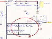
are this the ONLY way to measure full range ? multiple range such as 50V; 100V; 150V; 200V; more circuit complexity, as well as MCU programming. bad idea.
is there a better way to measure output voltage 0~200V, while can have maintain accuracy; linearity?
(multiple range circuit is not working, just show as an example)
thank you 2hartanto,
some detail info that i intended to do here.
but,

are this the ONLY way to measure full range ? multiple range such as 50V; 100V; 150V; 200V; more circuit complexity, as well as MCU programming. bad idea.
is there a better way to measure output voltage 0~200V, while can have maintain accuracy; linearity?
(multiple range circuit is not working, just show as an example)
Last edited:
Hi Cllow, first forgive me if sometimes i don't fully understand you. English is not my native language.
I have zero experience with SMPS. I just learn the theory within 2 month. Maybe in 1 or 2 week i will have parts on hand to make my first SMPS. But maybe i won't have time to build it until next year ☺
I will help as far as i can ( and as long as i have time ).
I don't know what is your project goal and what is the purpose of those PSU. It might be help if you can tell more.
Divide the working range into 2, 3 or even 4 is not a bad idea at all. I will do that if i were you. Doing that with uC is not difficult at all. You can use analog switch or relay to select voltage divider you prefer. If this is something too complex/difficult and you want to avoid it; i suggest don't go any further to make Phase shifted PWM code. Use dedicated PWM controller IC to make life eassier..
I have design and build digitally controlled PSU with LM723. The microcontroller i use don't have AD/DA so i use external AD/DA. The DA send voltage 0 to 2.55V to LM723. I set the feedback voltage divider ratio to 5:1 so i get adjustable voltage up to 12.75V in 50mV step. I forgot the exact lower limit but maybe arround 3V. So what i get is 3V to 12.75V digitally controlled PSU. Then i use AD to read the voltage and show the result in LCD at 100mV step. I also add over voltage protection routine if something goes wrong with LM723 or the final transistor; if the output voltage reaching 14V i disable the whole system.
Jagd.Panther
New member
Looks OK. 2N3904/3906 beta droops heavily at 100 mA to 30 min (that means the peak drive current will be limited). Use 2sa1020/2sc2655, BD139/140.
GDT magnetizing current should be less than 100 mA or so. Unless you want to add an extra stage in GDT driver.
resonant
Hi, Jagd.Panther , thank you for guide me again :w):w).
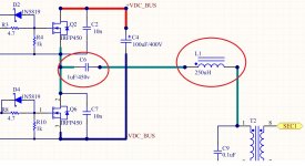
i need your opinion about resonant for below circuit:
while
Lx=T2pri + L1
Fr =100kHz
resonant = 1/(2*pi*sq(Lx*C6)) = 100KHz
Lx inductance could be variants due to lay-out & T2 leakage inductance.
my question is , using Oscilloscope to see(waveform), is the only method to determine ZVT transience, at that timing is the highest current ?
best regards
Looks OK. 2N3904/3906 beta droops heavily at 100 mA to 30 min (that means the peak drive current will be limited). Use 2sa1020/2sc2655, BD139/140.
GDT magnetizing current should be less than 100 mA or so. Unless you want to add an extra stage in GDT driver.
Hi, Jagd.Panther , thank you for guide me again :w):w).
i need your opinion about resonant for below circuit:

while
Lx=T2pri + L1
Fr =100kHz
resonant = 1/(2*pi*sq(Lx*C6)) = 100KHz
Lx inductance could be variants due to lay-out & T2 leakage inductance.
my question is , using Oscilloscope to see(waveform), is the only method to determine ZVT transience, at that timing is the highest current ?
best regards
Last edited:
Jagd.Panther
New member
C3,C8,C14,C17 should be low ESR/ESL ones (like ceramic caps). What is AL for your EE13 core?View attachment 5692
looks better now.
Jagd.Panther
New member
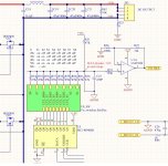
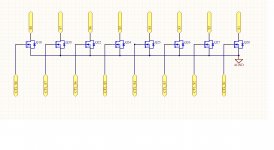
View attachment 5693View attachment 5694
more & more excited & complex, do u agree ? but i still have no clue how to get 200v measurement range.
16 raw dataline to get 200v range, very rare ;ww:;ww:
thinking using digital adj variable resister IC.
What resolution are you after? 50 mV? 100 mV? 250 mV?
Jagd.Panther
New member
That's true for unloaded transformer only. Did you check appnotes for phase shifted ZVS SMPS?Lx=T2pri + L1
View attachment 6_PSFB_discrete_drive.pdf
page1, simplify pri-coil current limiter. secondary channel turn-on/off Vds slope is differance.
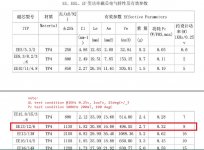
EE13 taken from phone charger(made in china) 5V@0.8A, i think EE core from china manufacturer
page1, simplify pri-coil current limiter. secondary channel turn-on/off Vds slope is differance.

EE13 taken from phone charger(made in china) 5V@0.8A, i think EE core from china manufacturer
That's true for unloaded transformer only. Did you check appnotes for phase shifted ZVS SMPS?
PSFB not related to resonant, i 've same doubt too, but i saw a digital powersupply(made in china) which using PSFB+LLC, i've limited info on this application note.
http://www.dianyuan.com/bbs/1499644.html this product is going to sell to whole world, new version is under testing.
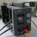
anyone have info for PSFB+LCC digital powersupply ?
What resolution are you after? 50 mV? 100 mV? 250 mV?
VO : output
R_ratio: voltage divider resister ratio
MCU measurement range : 0~3.3v / 10bits
level-shift :10v--> 3.3v
analog error :resister 1% + opamp offset
due to analog error is fix constant value, can be easily added in MCU's programming
Vo =30v range
3.22mV * R_ratio = 9.66mV resolution while: R_ratio=3.
Vo =50v range
3.22mV * R_ratio = 12.88mV resolution while: R_ratio=4.
...and so on...70V...90v...110v...
i need 200V range, so far i can get 190V range with digital range at 8 bits
Last edited:
moghimimahdi
New member
hi
i used ucc3895 for a phase shefted smps , it work correctly , but i cant make a good fb loop for that , can help me?
i cant make a fixed compansated FB loop , it make ringing
is this chip a current mode ic?
i used ucc3895 for a phase shefted smps , it work correctly , but i cant make a good fb loop for that , can help me?
i cant make a fixed compansated FB loop , it make ringing
is this chip a current mode ic?

