PIC Controlled MP3 player

Am starting to gather parts to embark on a pic controlled SD card based MP3 player i already have the following parts:

1) 16F877A - DSPIC30F4011J just in case i lack program space on the 16F877A

2) VS1053B- VLSI mp3 decoder ic which has a built in DAC and can decode any MP3 stream sent to it even internet radio if you have an ethernet based mico but you will need SRAM or DRAM to store the stream before sending to VLSI1053B it could even apply for an sdcard player

3) Micro SD card holder/ SD card adapter and micro SD card sockets

Next step:
1) Currently studying VLSI1053B datasheet
2) FAT16/32 file system study to read the mp3 data
3) Voltage levels matching as the VLSI1053B requires 3.3V based signals

Anyone did something like this before?
 
16F877A Dev board

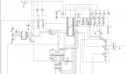
Ater a long time searching and planning i have almost completed by 16F877A Dev board before goign for the VS1053B the schematic is attached 16F877A Dev Board.JPG
 
Next steps

After some long time not taking care of this project i am slowly goign forward with it. Currently one thing is clear is that 16F877A on its own does not have enough Ram memory to run the MP3 player though i have just completed a development board for it. External RAM has to be added as reading a SD/micro sd card requires that at minimum 512bytes are read at ounce and sent to the VS1053 who on its own can process more than that at ounce. I am currently preparing to build the following:

1) Using a microsd to sd adapter and soldering wires to get the pins to run the microsd card in SPI
2) Already have 3.3 and 1.85V available on my bench supply as the VS1053 uses 1.85V for its internal circuitry and 2.7- 3.3V for the rest.
3) Building a DSPIC30F4011 dev board to run everything
 
I have move a little bit with this project. I am currently sending commands to the SD Card to get response back but i have to ind my way through the card is not responding. SD cards boot up in a native mode and they have to be set to SPI mode which i am currently trying to do.
Another point is that its easier to set the pic to use 3.3V instead of using resistors like its shown on many web it does disrupt the signals when testing on project board
 
I finally managed to intiialize the card to SPI. there are two commands to be sent to the card:

1) CMD0 used to set the card to SPI mode

2) CMD1 use to initialize the card

both commands have the arguments and CRC specific to them but its easy to build up a function or routine and re-use it continuously. My next command is CMD17 which is used to extract data. The card minimum data storage unit is 512bytes and my pic's RAM is only 368bytes less what is required to run the program.

The good news is that in SPI mode the sd card sends the 512bytes as 512 series of 8 bits maybe things could or could not work here. Even in case they don't i have 23A640 SPI Ram i bought from ebay and my DSPIC30F4011 board is ready i will post a picture of these soon
 
Reading SD Card Data Successfully

I have been able to read data from a 2GB card successfully and its attached. The tab MBR(master boot record) is the first part that has to be read from a FAT32 drive and the LBA begin address guides to the location of the FAT itself which i have to check properly. The issues met here are:

1) Sending a 32 byte or more using an 8bit pic is possible by breaking it into 8 bit chunks and sending continuously

2) Avoid doing anything else than transmitting through SPI so as not to slow things down

3) Clock idle Polarity i.e. CKP bit in SSPCON register can be high or low irrespective the device will clock to it. Microchip uses CKP high and i have used CKP low without any problem (don't run it at several MHz am using FOSC/64 i.e 312KHz but don't go below 100KHz)


4) Data sent by the device in this case the pic needs to be clocked with CS low. Waiting to receive spi data does not generate a clock. To keep the clock running the concept is always transmit 8 bit data whatever it does not matter it can be e.g. 11111110 (254 in decimal) just to keep the clock running followed by the SPI receive command.

5) At this stage for debugging purposes an LCD is completely useless and too slow instead i am
using the USART register and only the Tx line to display whatever i want to debug in Tera Term
Pro 2.3 http://hp.vector.co.jp/authors/VA002416/teraterm.html

6) A CP2102(plenty of boards available on ebay $2.5 and up) is adequtely suited to send data to the pc from the pic via USB and it can accepts 3.3V levels or 5V without any modification. the data in the excel file is a copy paste from tera term pro. the device appears as a COM port on the pc and to tera term pro


thats it for now until i move a little bit more. One last thing the whole bunch of data seen is for a card containing nothing more than 1 text file. most of the bits there are indicative of technical details and thats my next step which is to find my way through all this
 

Attachments

  • Book1.rar
    28.5 KB · Views: 36
Last edited:
Its well on its way the Sd card reading is working fine the next step is to move ahead with reading the contents but as usual something else came in between. my program needs to be re-thought as right now am telling the program to go and read the precise bits i need rather than list all of them. A minimum card read returns 512 bytes which i already knew would be too big to fit on a 16F877A and according to a test not even on a DSPIC30F4011

I am right now learning how to use an cortex m1 or stm32discovery board and i also have purchased a cortex M4 board from ebay. These devices have plenty of resources. Getting started is a bit more annoying cmpared to microchip as ARM provides something called the CMSIS library and ST also provides additional libraries. Its annoying at first start but once you done flashing the leds on the board and got the button to work its easy to go forward.
Another great thing compared to Microchip is that these devices are built with debugging in mind contrary to Microchip where debug headers have to be purchased seperately. I'll keep posted.
 
Adapter boards and next step

Project is still on its way i have to shift on how to make the USART port work on the STM32F0 board which is one step done. Next i need to get the SPI port running on the STM32F0 eval board.
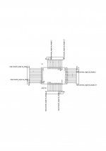
The main reason why i am moving to this microcontroller is that VS audio recommends not to connect SD cards on the same SPI lines as the VS1053B. I have built an adapter board for the VS1053B i will upload pictures but in the mean time this is the apdapter board pcb and silk VS1053B adapter schematic.jpgVS1053B PCB+ Silk.jpg. I did not bother to shape the board to a specific size but we'll see how it goes
 
I am still continuing with the project though I left it aside for a long time. I have cleaned up the code and made a cleaner hardware implementation for the SD Card. Instead of using 3.3V through out the circuit I have used a CD4050BE as a buffer that can translate the 5V pic signals to 3.3V level for the SD card. Another thing I ran into is hi tech c compiler used in PRO mode for my project was not compiling the code to do exactly what I coded in C. It took me weeks to find this out. I am back to lite mode and continuing with the project
 
Hi Microsim, thanks for the reply I am attaching the signals captured from my working unit. everything attached are the signals sent out to the Micro Sd card from the microcontroller. In order to avoid issues as I keep working on it I now have the microsd responding to the initialization command both from a pic16F877A and a STM32F100 eval. Both are working fine. I need to go further and send the other commands to the card until I am ready to read the FAT32 structure. I will see if I can carry on with both the pic16F877A and the STM32 as I continue. One thing to note here is that a clock frequency of around 100-200KHz is fine for the device to work.
 

Attachments

  • ARG0.bmp
    219.4 KB · Views: 12
  • ARG1.bmp
    219.4 KB · Views: 1
  • ARG2.bmp
    219.4 KB · Views: 3
  • ARG3.bmp
    219.4 KB · Views: 2
  • CMD0.bmp
    219.4 KB · Views: 1
  • CRC0.bmp
    219.4 KB · Views: 4
How to read a FAT32 formatted Micro SD card:

In order to find a way through FAT32 I have used two software which have been very helpful a) Winhex b) Active Disk editor

The FAT32 is read in this order:

1) Read Sector 0 AKA Master Boot Record

2) go to the Logical FAT from Values read from MBR and read values here

3) go to the root directory to get the first cluster of each file

4) Go to the File Allocation Table find the next clusters for the file and read the clusters

I have to complete step4 above.

its easier first to build an excel sheet with formulas, make sure the calculations point to the correct location and then implement the code.

As I complete the equation for step 4 I will post some more updates
 
I finally managed to complete my way till the last drop there is to understand for FAT32 structure and I can navigate easily through now by calculating and specifying my own calculated sectors that hit right on target to find files and their cluster chains. This link was extremely useful http://www.pjrc.com/tech/8051/ide/fat32.html
I kept looking everywhere on the net but kept coming back to it and found all my answers inside. To make sure my FAT32 algorithms were correct I built an excel sheet with formulas and experimented with Winhex and Active disk editor for both a USB disk and a Micro sd card. What's great about the FAT32 is that independent of whether its implemented independent of the hardware, the same logic applies to find the files. I have some old IDE hard drives I am planning to hack through with. I did notice a small difference in where to read the first sector but otherwise the rest is the same.

Next step is to implement the algorithm on the pic and the STM32 and ensure they work properly.
 

madphil

New member
Hi Zeus_threat, have been myself trying to understand fat32, and it has been driving me nuts.
It would seems that I must be going wrong somewhere and cant fathom it out... grrrrr
I've been looking at the MBR(sector 0) and have been multiplying various (what i think numbers) to give me
an address either in sectors or clustors which takes me to the fat file.. but so far nothing.. can you
please please let me know how you did it..

Thanks Phil :)
 
Hi I am currently thinking of whether I continue with using my own FAT library, use FAT FS or change the control from SPI to SDIO. I'll decide and keep posted
 
Top