Problem with IR2153 SMPS

MyFirstSMPS

New member
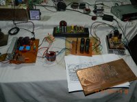
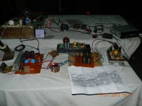
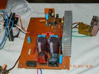
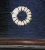
I found today some time and did a new Current Transformer and replace some of a damaged components on PCB, tomorrow I hope test my SMPS again.
In addition, I found the one unforgivable failure, which I have previously unnoticed.
Namely, the old Current Transformer windings connected to wrong way:eek:, perhaps there is also the opportunity - why destroyed MOSFETs and IR2153 itself?
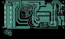
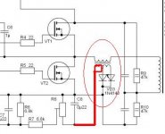
Below picture of this connection scheme.
And it is interesting that, in this case worked for my SMPS until the outputs connected in series and loaded. Independent output and loading of them is not influenced by the work of SMPS even ~240V main power.
Based on this false association could say that the IR2153 is a fairly durable IC than in this situation, even a short time can work:"::. As the diagram shows it was one of my current transformer secondary windings is essentially short-circuit winding, therefore no C/T - there was only one winding in use((@.
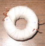
Now this problem is eliminated, based on the bad experience with Power Transformer, Current Transformer also got better insulation (PTFE). Windings consisting of a double varnish and additional layer of silk-fiber 0,26mm copper wire which before was produced mainly in the high-frequency inductive coils.
Power Transformer inductance is also lower now than it was last - measured 4.793 mH (milli-Henry) is now
I hope this new design is better now:w)?
 

Attachments

  • power transformer1.JPG
    power transformer1.JPG
    71.3 KB · Views: 83
  • current transformer1.JPG
    current transformer1.JPG
    92 KB · Views: 87
  • wrong CT.JPG
    wrong CT.JPG
    19.9 KB · Views: 207
have you tried to buffer the IR2153 output it helps in increasing available current to charge the mosfet and some people have reported that it prevents the ic being destroyed if the mosfet blow
 

MyFirstSMPS

New member
have you tried to buffer the IR2153 output it helps in increasing available current to charge the mosfet and some people have reported that it prevents the ic being destroyed if the mosfet blow

No, the initial testing of the same scheme, which is first post.

Today I've been busy and have little to do with this SMPS, but in the evening, I hope, however, try whether the new transformer prove to the job. Today I got a couple of old Fiskars UPS, only the batteries run out, working equipment itself, big and powerful - demolition and found a lot of parts, I think I can use them in the future SMPS - a lot of IR2110 drivers, N27 material cores E65, lots of powerful transistors and colossal heatsinks:UP::UP:((@.

Anyway, after some time today, can see if IR2153 SMPS test and then writing how this thing is.
 

MyFirstSMPS

New member
The (another) first test, driver IR21531PBF

Now is the initial testing of SMPS made 100V input voltage, SMPS worked for half an hour. Initially, the fuse instead of the 75W incandescent bulb, this will help to better regulate the overload protection and also helpful to see whether the SMPS is done correctly. But even here a lot written this method and is recommended.

Overload protection also seems to now be working correctly:) because the output was loaded (light bulb) and the first electric grid switching, filament, instead of a fuse winked a few times and then the light went out. By adjusting the trimpot R8 was a moment when the light was permanently flashing and the SMPS output was also voltage. Output voltage is low, firstly only +-4.5V but the secondary rectifiers that are no hot – very good news for me:).
Low output voltage is probably due to the input incandescent and to low input voltage - 100V.
!!!:Or can be a problem ???


OK, now increase the input voltage and see if SMPS it works close to the main voltage:D.
When working, then filament replacing the fuse and perhaps then also works.
 

MicrosiM

Administrator
Staff member
Keep Lamp connected in series with your SMPS, EVEN if your SMPS is fully working.

One mistake or small fail in your setup, That LAMP may save your life!

SMPS is not a Joke, either they JOKE when they blow. they just blow, and they dont care what they are blowing!


I think that your setup is 40% in good condition, While I think its necessary to show some oscilloscope waves, that will help us to tell you whats going on

Good Luck

And be careful!
 

MyFirstSMPS

New member
While I think its necessary to show some oscilloscope waves, that will help us to tell you whats going on

Good Luck

And be careful!

Thanks for good wishes, but yet...


It may be a problem at the moment. My oscilloscope is quite old and I do not have a suitable voltage probe. Currently capable of measuring only 20+20 V (peak to peak). It is not enough.
This is a normal input impedance oscilloscope but the capacitance is different (40pF) and I could not find anywhere an acceptable cost suitable probe. I investigated the possibilities to do it myself but I have to be further investigate.

Should be suitable after all 1:10 probe? 1:100 probes have been inaccessible to me. Is a oscillograms I have to measure the SMPS input voltage 230V? Or would some kind of insight for example ~150V input voltage? What exactly would want to see oscillograms - the shape of the MOSFETs gate signal? Or another measuring point? Then what exactly? I have an three isolation transformer so there would be no problem to connect SMPS and the oscilloscope, both galvanic separation in mains. There is also auto-transformer (VARIAC) for SMPS, as previously stated. So – can I use 1:10 probe?
 

MicrosiM

Administrator
Staff member
Thanks for good wishes, but yet...


It may be a problem at the moment. My oscilloscope is quite old and I do not have a suitable voltage probe. Currently capable of measuring only 20+20 V (peak to peak). It is not enough.
This is a normal input impedance oscilloscope but the capacitance is different (40pF) and I could not find anywhere an acceptable cost suitable probe. I investigated the possibilities to do it myself but I have to be further investigate.

Should be suitable after all 1:10 probe? 1:100 probes have been inaccessible to me. Is a oscillograms I have to measure the SMPS input voltage 230V? Or would some kind of insight for example ~150V input voltage? What exactly would want to see oscillograms - the shape of the MOSFETs gate signal? Or another measuring point? Then what exactly? I have an three isolation transformer so there would be no problem to connect SMPS and the oscilloscope, both galvanic separation in mains. There is also auto-transformer (VARIAC) for SMPS, as previously stated. So – can I use 1:10 probe?


please read:- http://www.diysmps.com/forums/showthread.php?72-Necessary-Equipments-needed-for-SMPS-development.


You will Need 100:1 Probe, no 10:1 in SMPS

You MUST use isolation transformer for your oscilloscope, AND if possible for SMPS (for extra safety, While you have more than one)

oscilloscope used to measure S+D, S+G of each Mosfet and show waves, and many other mesures in SMPS

Variac is also important, while you have it, then USE it


Hope that helps
 

mazyar-b

New member
hi
i make a pcb for my smsp driver and i must say , i use the circuit for driving an ultrasonic cleaner , so when i use it under 60 volt it seems work goood and nice , but in 220 volt circuit take more more current and finally the mosfet that i used going to dead , point is here when i use circuit with out an output , i repeat , without a load , half bridge self take so much current in some frequency like 40khz or 75khz or .... , i ask you dear friend why happened this . why ?
 

dinithm

Member
failed.jpg
first time turn on - it work fine voltage ok 14.7v, load 4.7ohms
after 30sec - turned it off ,no heat no problem

second time turn on - (load 4.7ohms)
PCB burned AND fused,
2 fet (irf840) burned


three times rebuilt it same result,

Screen shot 2013-01-07 at 2.39.33 PM.jpg
1.jpg
2.jpg
 
Last edited:

MicrosiM

Administrator
Staff member
first time turn on - it work fine voltage ok 14.7v, load 4.7ohms
after 30sec - turned it off ,no heat no problem

second time turn on - (load 4.7ohms)
PCB burned AND fused,
2 fet (irf840) burned


three times rebuilt it same result,


Did you turn on the SMPS the second time while there is a load at the output?
 

michelle

New member
Ir2153 smps

Hello
greetings this schematic is tested as shown in pics IR2153 used in both smps one is with totem configuration HOPE THIS HELPS YOU

warm regards
michelle
 

Attachments

  • DSCN3713.jpg
    DSCN3713.jpg
    267.7 KB · Views: 108
  • DSCN3731.jpg
    DSCN3731.jpg
    123.7 KB · Views: 128
  • 84_1347179361.gif
    84_1347179361.gif
    26 KB · Views: 250

michelle

New member
totem

Hello
greetings i used BD139 BD140 FOR totem just adding another pair of irf460 as shown in schematic
warm regards
michelle
 

Attachments

  • 2423084200_1357532001.gif
    2423084200_1357532001.gif
    8.8 KB · Views: 170

michelle

New member
Ir2153 smps

Hello
greetings need over current protection is current sensing transformer good idea or is their better method for ocp and short protect
warm regards
michelle;)
 

Attachments

  • smps 1.jpg
    smps 1.jpg
    227.2 KB · Views: 120

michelle

New member
smps test with dclass 2KW

JUST A SMALL TEST of smps IR2153
 

Attachments

  • DSCN3806.jpg
    DSCN3806.jpg
    259.6 KB · Views: 82
  • DSCN3803.jpg
    DSCN3803.jpg
    216.8 KB · Views: 52

michelle

New member
Overcurrent protection for ir2153 smps

Hello
greetings can this overcurrent protection using 555 ic and current sensing transformer be used as this is a higher power smps
warm regards
michelle:"::
 

Attachments

  • igbt_3.gif
    igbt_3.gif
    28.5 KB · Views: 190
Top