Question about current regulation for half bridge unregulated 15V SMPS

Svele

New member
Hi from Belgrade, capital of Serbia!
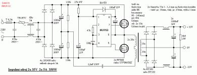
I have a question - how to make current regulation for half bridge (schematic is in the attachment) from 0 to 30 A, for high current car battery charger 12 V / 30 A max. Output voltage is not regulated, only current.
The idea is only to connect SMPS as a batt charger to a car battery and then charge with preregulated amount of current (with some potentiometer), voltage will drop at the beggining and then rise as battery charging.
Please help me to solve this issue.
Greetings from Serbia!iz_2_35.gif
 

Svele

New member
I almost forgot!
On secondary site will be a graetz bridge and electrolytic cap and only one secondary winding, without a choke!
 

Silvio

Well-known member
I almost forgot!
On secondary site will be a graetz bridge and electrolytic cap and only one secondary winding, without a choke!

With this chip IR2153 is not possible to make variable current regulation. You can only make total shut down when over current.

Silvio
 

Svele

New member
Thank You!
Could I add some other IC as a current regulator? I need current regulation and IR2153 because IR is irreplaceable as a cheap half bridge IC?
 

Silvio

Well-known member
Thank You!
Could I add some other IC as a current regulator? I need current regulation and IR2153 because IR is irreplaceable as a cheap half bridge IC?

I already told you to control current you have to control pulse width. The IR2153 cannot do that.
 

Svele

New member
Could You advise me what IC I need to apply for above schematic (accu charger up to 30 A current regulated)?
Thank You in advance!
 

Silvio

Well-known member
The IC is UC3845 which is a current mode pulse width modulator. The circuit for it is totally different as this is a flyback mode controller. You have to find a suitable circuit and enhance the current by using a larger transformer and a larger mosfet and diode which can handle the output current needed.

For flyback operation the transformer needs to be larger than that is used for the previous circuit as in flyback mode only the first quadrant of the flux is used.

If you are not so keen on power electronics I suggest you don't try to build it as you will be in for surprises. It is not so easy as it seems. 30 amps is quite a bit of current and care must be taken in the design. Personally I do not have a circuit for this chip but if you want to try something then you can download the datasheet for a start to take an idea. Then you can search the internet for a suitable circuit diagram.

Regards,

Silvio
 

Svele

New member
Thanks for information!
I will try with some other transformer. I already had the calcs with a big one from ATX PS...
 
Top