Scale able class D 1250W UCD style and Non-UCD style - PCB Ready. Tested.

norazmi

diysmps Senior Member
Hi,

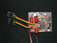
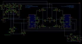
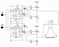
i`m gonna to post hi-end class D pwm base on IR2110 + LM311 for UCD style and IR2110 + TL074 for non-UCD style. This amp already tested and i`ll post for both circuit + pcb + silk. Most of us already understand when implement into class D pwm will face few adjustment to apply with suiteable power rails. Also to measure dc at output is omportant because it can burn @ damage your speaker without correct connection. My suggestion if u include dc protection for this amp and if u can apply short circuit protection connect to SD mode at IR2110. Unfortunately i`m not done yet with SD protection and only depends on fuse at each rails + DC protection. So far so good and never blow any mosfet yet since 1 year running this module. I`ve build both UCD and Non-UCD style, nothing much different, but with LM311 we need good filter at input signal. Its very sensitive pwm need to proper filter to avoid any EMI with others electronic devices.

Credits goes to owner ejtagle from foros de electronica forum :D . here you go for hi power class D pwm module. I believe there are many modules on the net and also here in diysmps forum. I hope all of u like it.

regards.
Azmi
 

norazmi

diysmps Senior Member
UCD style schematic and PCB

this is UCD style complete with schematic and PCB
 

Attachments

  • IR2110 UCD.pdf
    1.6 MB · Views: 5,886

norazmi

diysmps Senior Member
Non-UCD schematic

this is NON-UCD style complete with schematic , i forgot where is the pcb file located, i`ll try to find out.
 

Attachments

  • clase d 074 con IR.pdf
    72.5 KB · Views: 3,435

michelle

New member
Thank you

Hi Norazmi
greetings thanks for posting i am making iti appreciate your efforts of posting tried tested circuits
warm regards
michelle
 

norazmi

diysmps Senior Member
nvm michelle.

make it with care, like u make simple class d before, sure it will success :D
 

michelle

New member
Class d

Hi Norazmi
greetings i made amp and powered it its come on no distortion very very clear sound but
audio power is only about 20 watts just few things i want to clarify

1 gate resistances are 27 ohms is it ok
2 what voltage did you get on emitter of TIP 31C i am getting 24 volts thats supply pin of IR2110 pin 9 and pin3
i will send you high def pics for you to see if any component is wrong rest amp is clear no distortion
supply 40 volts dc i used ceramic cap 330pf in feedback i have siver mica 1% should i use it ill keep you
informed
warm regards
michelle
 

michelle

New member
CLASS D high power

Hi Norazmi
greetings just want to know why 2 TIP31 are used in pcb and component layout but schematic shows one TIP31 trying to figure out whats wrong
warm regards
michelle
 

norazmi

diysmps Senior Member
Hi michelle,

gate resistance is depend on what type of mosfet do u use, if u look at original schematic its use irfp250, but if u can get good mosfet with low rds-on you can even lower the resistor gate, such as irfb4020, irfb4019, irfb4710, irf540z and etc.. i use irf540n with 22 ohm gate resistor with +45 0 -45 vdc, because irf540 have lower rdson than irfp250, and more cool.

for the tip31c if u see on the schematic, its clamp with 12v zener diode, so the output will be 12v or less. and i`ve got 12vdc also. you need to measure with emitter of tip31c with -ve rails, do measure it with ground you will get wrong data :p.

for your information, ceramic is better, because ceramic is well known best working at high freq :D.

for the tip31c have 2 on the board, because if you look carefully at the design they put both version of the pcb together, 1 is for to-247 will use upper tip31c as a supply to fix with to-247 position, and if you use to-220 as output transistor you can solder tip31c below, so it will fix with output transistor for easy to mount at heatsink. :D .

hope u can get that, yea if u have any picture, please post it here. i`ll take a look at my pc if i have sample picture for reference.
 

MicrosiM

Administrator
Staff member
Class-D Mosfet

Hello


Attached is a MOSFET specially designed for CLASS-D amplifiers,

At least, you may take the specification of this Mosfet, and make your selection based on it

Enjoy :D
 

Attachments

  • MOSFET_CLASS_D.pdf
    247.6 KB · Views: 3,370

michelle

New member
CLASS D high power

Hi Norazmi
greetings just one pic yes voltage is correct on emitter of tip with reference to negative rail.


Warm Regards
Michelle
 

Attachments

  • DSCN2688.JPG
    DSCN2688.JPG
    338.8 KB · Views: 1,489

norazmi

diysmps Senior Member
nice one michelle, how does it sound?, i`m never tried irfp package yet, on your pic i`ve seen u put 1uf caps on each rails which make ur board not suiteable for arrangement, u can use 100nf caps x 3 on each rails if u cant get 1uf 63vdc to mount, and for exchange, make one power supply board and put 1uf caps filter on +ve rails and -ve rails together with aliminium caps lets say 4700uf on each rail. :D

so u can mount to247 together with with tip31c. also u can make adjustment with photoshop or ulead photoimpact to modify the board suiteable for you, make it compact as possible because in class D long trace is matter.
 

norazmi

diysmps Senior Member
Hello


Attached is a MOSFET specially designed for CLASS-D amplifiers,

At least, you may take the specification of this Mosfet, and make your selection based on it

Enjoy :D

LOL, i hope i can get this mosfet soon , this one will be best sounding and pushing hard even it will remain cool,

btw michelle tip31c will get little hot and u need heatsink for it.
 

michelle

New member
CLASS D high power

Hi Norazmi
greetings well managed to make it on mistake was 47k and 820 ohms interchanged if you zoom my pcb you can see my mistake i post full results tomorrow have to attach heatsink
warm regards
michelle
 

michelle

New member
mosfet choice

Hi Microsim
greetings well just want to ask you mosfet choice
1 IRFB 4103 rds on@10 volts is 139Mohms
2 IRFB4227 rds on@10 volts is 19.7Mohms
which is better for D class amp its just my begining in Dclass amps can you advise me
warm regards
michelle
 

norazmi

diysmps Senior Member
ouch, nice to hear that your amp still working, well.. change it to correct value and tell me how does it sounding by using to-247 package, michelle if u want more power, u can bridge it by using 2 ir2110, i have bridge topology i`ll attach it. I`ll try to answer your question to Microsim, i can say still IRFB4103 pwn IRFB4227, low thd, more clear sound and it can push it to maximum power 300w 8 ohm, 600w 4 ohm, 1kw 2 ohm, remember the lower ohm speaker impedance need to adjust rails voltage of the amp 65-75 vdc for IRFB4103 will do, for high power need more protection, at least dc detect and delay turn on, better if we can do short circuit protection too. Yeah do not forget fuse at +v and -v rails. My ucd bridge only with irf540N and run at + - 45-48 vdc 12 amp trafo can pawn 4 pcs 15 inch speaker with no heat and burn, only power supply fuse blow because at that time im forgot to change to higher ampere, imma using 5A slow blow at each rails, now change it to 8Amp and not blow it yet.
 

Attachments

  • ir2110_bridge_716.jpg
    ir2110_bridge_716.jpg
    38.8 KB · Views: 685
  • driver_102 bridge.jpg
    driver_102 bridge.jpg
    35.2 KB · Views: 1,034

michelle

New member
really powerful amp

Hi Norazmi
greetings thanks for HELPING me to make one more class d amp sound is very good
have been reading about performance of this amp on foros de electronica for along time in fact i started
this thread on diyaudio this pcb i posted today is the pcb i posted on diyaudio it never worked fake ir ics
so i gave up after your posted that it is easy to make i dug this old pcb started it on powering amp got dc on output lol thought again i fail changed ic sockets amp had low output on checking components
found out my mistake R7820 OHMS and R14 47K WERE NOT IN correct place as you can see on my pcb
on interchanging postions amp came on full powerR7 NOW is 560 ohms am i correct gate resistances
are 27 ohms ONLY PROBLEM is t106_2 core looking where i can buy from i dont believe in substitutes
slowly learning d class you really have helped me a lot and i hope many diyers will make it these are good amps to learn d class i want your advice i want to make redsign new pcb especially some tracks
near 2n5401 are to thin is it ok if tracks are a little thicker i have many dc protectors but i have never
seen any SHORT CIRCUIT good protection schematic that we can implement for this amp hope i can find one looking forward for more help from you will make bridged version soon sorry to trouble you
ADDICTED to amps
warm regards
michelle
 

norazmi

diysmps Senior Member
good, im also thinking to contribute more, with protection, and bridge mode. Michelle do you have any ferite core? maybe taken from faulty TVs or faulty PSU. Or u can take toroid core from car power amp transformer, and remind u that ferrite core need to have air gap. Last time im buying T106-2 core from amidon corp.

With IRFP250N u can stay with 27 ohms gate resistor and dont lower it down may cause the mosfet unstable and blow. its ok to redesign or u just use photoshop u make new trace and adjustment, i think that would save ur time also.

I`ve few idea for the protection, but its good if Microsim help us :D . Because he know alot about high frequency smps and class D. My plan is to use LM555 and SFH610A-1 for for protection . im not design yet for the circuit, i need little time to calculate it. but if anyone expert here mind to help it would be more faster.
 

irvynejay

New member
ferrite core

i also have this core measures 1.4 cm thickness 1.9 cm inner x 3.1 outer
 

Attachments

  • DSC_0136.JPG
    DSC_0136.JPG
    404.8 KB · Views: 298
  • DSC_0134.jpg
    DSC_0134.jpg
    116 KB · Views: 214
  • DSC_0135.JPG
    DSC_0135.JPG
    412.1 KB · Views: 207

michelle

New member
schematic

Hi Norazmi
greetings do you have clearer schematic the one you posted post 15 the one with black background if you send clear schematic i can design pcb for it its worth a try
warm regards
michelle
 

michelle

New member
mosfets for d class

hope this helps
warm regard
michelle
 

Attachments

  • 150 - 1.jpg
    150 - 1.jpg
    126.9 KB · Views: 419
  • 200.jpg
    200.jpg
    138.4 KB · Views: 236
Top