You are using an out of date browser. It may not display this or other websites correctly.
You should upgrade or use an alternative browser.
You should upgrade or use an alternative browser.
Scale able class D 1250W UCD style and Non-UCD style - PCB Ready. Tested.
- Thread starter norazmi
- Start date
Everything was fine until today, irf540z was cold (no heatsink) and worked good on 4ohms load, but now failed. After couple seconds fets become over +70C, sound like underground... Irf540z with 22ohms+ 1n4148 , T106-2 1mm 37turn+ 0,47cap Any suggestion where to search problem?
+- 70vdc is overkill for irf540z, i suggest you use to247 package , and you will be suprise about the sounding and power, try irfp260N with 47 ohm gate, minimum 22uh inductance, there is alot diff between to247 package and to-220 package, reduce fsw 250khz. also you can add totem pole easily to reduce stress on ir2110.
It was 70celsius, i fixed , was problem with ir2110(killed ic and fets couse found that input wire crossed output wires), now its alive, +/-49v same irf540z. On 4ohms ferrite core heat up to ~50celsius, mosfets maybe 40celsius (after 2-3min play music max volume) without any heatsink+- 70vdc is overkill for irf540z, i suggest you use to247 package , and you will be suprise about the sounding and power, try irfp260N with 47 ohm gate, minimum 22uh inductance, there is alot diff between to247 package and to-220 package, reduce fsw 250khz. also you can add totem pole easily to reduce stress on ir2110.
Hi all.
In past I did this one who is feedbacked pre and post and does very low distortion.
I have use in sim a chip who has programmable deadtimes, en I did see that the mosfet
mention here is even better with it's low nC.
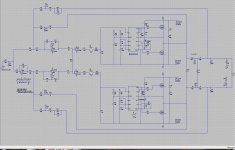
This schematic is a three level, less stress on mosfets and give a double frequentie on output.

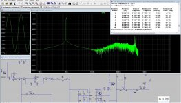
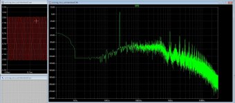
25 Khz plot

Schematic

regards
In past I did this one who is feedbacked pre and post and does very low distortion.
I have use in sim a chip who has programmable deadtimes, en I did see that the mosfet
mention here is even better with it's low nC.
This schematic is a three level, less stress on mosfets and give a double frequentie on output.

25 Khz plot

Schematic

regards
Last edited:
irs900 amp is good and works well only if you do not remove the load which is the speaker while the amp is on .whether the volume is high or low it does not matter. the moment you disconnect the speaker from the amp while it is on , it becomes unexplainably unstablequick update.
been test both the tl074 non-ucd and the irs900d. the irs900d is a bit more robust and are not as susceptible to component error. i've even got the irs900d to work with 8-9uh when the non-ucd would just go unstable with that low inductance. the irs900d could also drive more mosfet without being too picky.
maybe because of the higher switching frequency, maybe because of the better logic input. haven't tried increasing the switching frequency to the same 280khz as the irs900d yet, but the rest of the component is the same. mainly irfb5615, 27ohm gate resistor, 1n5819 gate diode, uf4007 driver diode.
as both design are more or less stable with the test voltage, I'll be feeding them the operational voltage of ~65V next. will update more about my finding later.
have you managed to build this. kindly post photos of your buildHi all.
In past I did this one who is feedbacked pre and post and does very low distortion.
I have use in sim a chip who has programmable deadtimes, en I did see that the mosfet
mention here is even better with it's low nC.
This schematic is a three level, less stress on mosfets and give a double frequentie on output.
View attachment 7291
25 Khz plot
View attachment 7293
Schematic
View attachment 7294
regards
