Hi,
This is a project we propose to build:
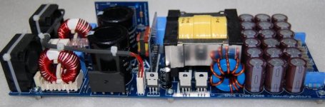
1200W - ETD49
2500W - ETD59
You archive all the variations below my proposed scheme, but basically you can choose what you plant and how they think of words that will arrange the SMPS.
From the start we wanted the source can be configured to a certain extent.
You can choose ETD49 ETD59 or to get up to 1200W or 2500W.
You can choose Gate driver transformer or integrated.
Also you can choose to use or SMPS reaction, in fact recommended if you want the look and power supply efficiency to increase by up to 20%.
You can greatly simplify the source by not using the auxiliary winding and fan control circuit.
Depending on the desired power you can still connect a pair of diode recovery.
Also depending on the power to choose the desired EMI filters.
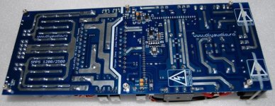
PCB successfully you up very high currents due to very strong design and very short routes.
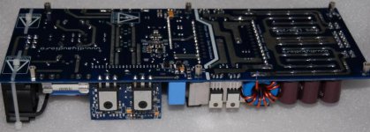
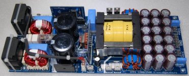
In the picture is not planted fan control module and standby power for tests I used an external source, but now the evening I put up this way and I'll come back with detailed photos.
SMPS can react or not, has short circuit and overload protection, fan controller and can ON / OFF - REMOTE.
Fan control is as follows: the source can go home for a few minutes with a predetermined maximum speed resistor, the maximum speed at startup with that role deprafuirea source and verifying the proper operation of fans. After several minutes reduces its speed fans that can be set from a potentiometer. Fan speed increases when the source is loaded with about 100W, if consumption is less than a threshold value starts the fan speed, the fan will continue to operate at high speed for another few minutes, then speed will be reduced, consumption at this time if the source increases, the fan will remain in high speed.
For high speed fan to start with is no longer necessary to "plant the following components: R43, R44, R45, C44, Q5, DM2, D19, planting these components makes the fan start to be slow, if amps look good HI END.
We can also provide a large part of the source components, the archive is a pdf OFERTA.PDF "with my constituents, you can buy the whole package or you can just buy the parts you are interested in detail.
Components "OFERTA.PDF" costs about 30 Euros for a set of PCBs.
Who would set the whole set of components and boards can benefit from planting all the components of labor supply at a price of 15 Euro for a set.
Transformer must be material ETD49/59 3c90, if you have high frequency and rapid Mosfeturi choose default 3f3 material.
To be the primary ETD49 2x11 - 2x12 90/105/120x0 wound with Litz wire, 1mm to get about 7-8V secondary to a spiral if the source has no reaction, if the source has to be calculated appx 6V reaction to a spiral wire must 120X0 be Litz wire, 1mm minimum.
To be the primary ETD59 2x8 - 2x9 120/135/160x0 wound with Litz wire, 1mm to get about 10-11V secondary from a spiral if the source has no reaction, reaction must be calculated if the source is appx 8-9V to spiral wire Litz wire must be 200X0, 120x0 or two at least 1mm, 1mm in parallel.
Data for ST-BY power transformer will be made available in a few days.
For this transformer (ST-BY) will be available in appx 1-2 weeks to a transformer winding for appx 3-4 Euro pretz or ferrite case and the price of 1.5 Euro.
If someone wants PCBs can offer the prices below, without shipping charges.
A set of PCBs (PCB 3) = 25 Euro / set
Two sets of PCBs (PCB 3) = 20 Euro / set
Three sets of PCBs (PCB 3) = 17 Euro / set
E-mail orders stosor[at]yahoo.com
Excuse the English used is not my native language I used google translate and then I made some corrections ...
I'm from Romania.
This is a project we propose to build:
1200W - ETD49
2500W - ETD59
You archive all the variations below my proposed scheme, but basically you can choose what you plant and how they think of words that will arrange the SMPS.
From the start we wanted the source can be configured to a certain extent.
You can choose ETD49 ETD59 or to get up to 1200W or 2500W.
You can choose Gate driver transformer or integrated.
Also you can choose to use or SMPS reaction, in fact recommended if you want the look and power supply efficiency to increase by up to 20%.
You can greatly simplify the source by not using the auxiliary winding and fan control circuit.
Depending on the desired power you can still connect a pair of diode recovery.
Also depending on the power to choose the desired EMI filters.
PCB successfully you up very high currents due to very strong design and very short routes.
In the picture is not planted fan control module and standby power for tests I used an external source, but now the evening I put up this way and I'll come back with detailed photos.
SMPS can react or not, has short circuit and overload protection, fan controller and can ON / OFF - REMOTE.
Fan control is as follows: the source can go home for a few minutes with a predetermined maximum speed resistor, the maximum speed at startup with that role deprafuirea source and verifying the proper operation of fans. After several minutes reduces its speed fans that can be set from a potentiometer. Fan speed increases when the source is loaded with about 100W, if consumption is less than a threshold value starts the fan speed, the fan will continue to operate at high speed for another few minutes, then speed will be reduced, consumption at this time if the source increases, the fan will remain in high speed.
For high speed fan to start with is no longer necessary to "plant the following components: R43, R44, R45, C44, Q5, DM2, D19, planting these components makes the fan start to be slow, if amps look good HI END.
We can also provide a large part of the source components, the archive is a pdf OFERTA.PDF "with my constituents, you can buy the whole package or you can just buy the parts you are interested in detail.
Components "OFERTA.PDF" costs about 30 Euros for a set of PCBs.
Who would set the whole set of components and boards can benefit from planting all the components of labor supply at a price of 15 Euro for a set.
Transformer must be material ETD49/59 3c90, if you have high frequency and rapid Mosfeturi choose default 3f3 material.
To be the primary ETD49 2x11 - 2x12 90/105/120x0 wound with Litz wire, 1mm to get about 7-8V secondary to a spiral if the source has no reaction, if the source has to be calculated appx 6V reaction to a spiral wire must 120X0 be Litz wire, 1mm minimum.
To be the primary ETD59 2x8 - 2x9 120/135/160x0 wound with Litz wire, 1mm to get about 10-11V secondary from a spiral if the source has no reaction, reaction must be calculated if the source is appx 8-9V to spiral wire Litz wire must be 200X0, 120x0 or two at least 1mm, 1mm in parallel.
Data for ST-BY power transformer will be made available in a few days.
For this transformer (ST-BY) will be available in appx 1-2 weeks to a transformer winding for appx 3-4 Euro pretz or ferrite case and the price of 1.5 Euro.
If someone wants PCBs can offer the prices below, without shipping charges.
A set of PCBs (PCB 3) = 25 Euro / set
Two sets of PCBs (PCB 3) = 20 Euro / set
Three sets of PCBs (PCB 3) = 17 Euro / set
E-mail orders stosor[at]yahoo.com
Excuse the English used is not my native language I used google translate and then I made some corrections ...
I'm from Romania.
Last edited: