You are using an out of date browser. It may not display this or other websites correctly.
You should upgrade or use an alternative browser.
You should upgrade or use an alternative browser.
SMPS 90W Viper100a / Myrra74050 : Whats wrong !?
- Thread starter kaip
- Start date
blasphemy000
New member
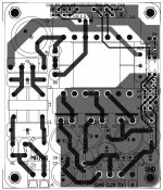
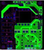
You didn't accidentally put the transformer or the VIPer IC in backwards did you? Those are the only two things that I can see that could possibly cause instant and catastrophic failure of your circuit. I mean, this is a circuit straight out of the datasheet with a transformer that is designed to work with this IC. Your layout looks fine from what I could tell. I didn't notice any misplaced traces or anything like that. As long as the transformer is soldered in the correct orientation and the tab/heat-sink on the VIPer IC is facing the outside of the board, I can't see any other reason to cause instant failure. Other than that, maybe one of the other components on the primary side was faulty out of the box and is causing issues?
PS - Can you post some pictures of your actual power supply? One top and one bottom picture would be great.
PS - Can you post some pictures of your actual power supply? One top and one bottom picture would be great.
Last edited:
Thanks for your reply.
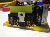
Here are some pictures of my prototype.
The wire on the bottom is a GND wire for one of the secondary caps. I managed to damage a through plated hole....
The fuse is also missing and it has not been properly cleaned yet
Now I will check the circuit without the Viper, and change the HighVoltage Electrolytic.
The one in the pictures is of dubious Chinese source
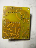
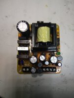
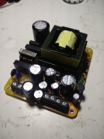
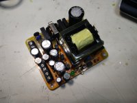
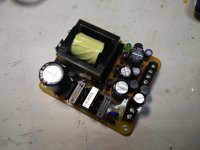
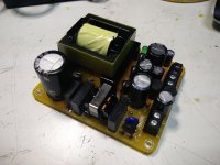


blasphemy000
New member
I have a couple of ideas of what might have happened. My guess would be that the VIPer100a IC is damaged and needs to be replaced and here is what I think may have killed it. I would also recommend that you replace D5 because if my idea is correct, it was probably damaged also. Maybe consider swapping in a 1A diode such as the BYT11 that you're already using in the snubber clamp, just for added reliability for the AUX supply section.
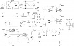
1.) I noticed that you have a jumper in place of R3(39 Ohms). The VIPer100a datasheet says that this resistor is optional but without it the IC can be subject to damage due to voltage spikes on the AUX line. These can be caused by lightning interference, but also by the sudden inrush voltage spike on the AUX line when the circuit first starts up. I don't think this is very likely to cause your failure, but I would install the resistor as a safety measure.
2.) This is what I think actually caused the damage. I think the voltage rating on your TVS diode(D3) is too high. The Drain-Source breakdown voltage of the MOSFET inside of the VIPer100a is approximately 700V. Exceeding this voltage on the drain pin can cause severe damage internally to the device. Your TVS diode is rated at 400V. Looking at the datasheet, the actual voltage can be anywhere from 380-420V at a testing current of only 1mA. As the clamping current increases, so does the clamping voltage, and at 2.8A of clamping current, the clamp voltage can rise to approximately 550V.
Your schematic has the input voltage labeled from 185-265VAC, at the lowest end of this rating(185VAC) your rectified rail voltage will be about 260VDC. During the flyback portion of the switching cycle, the drain voltage on the IC will be your rail voltage plus the clamping voltage of the TVS diode. So 260 + 400 = 660V This is getting dangerously close to the MOSFET's breakdown voltage even at the lowest of input voltage. Also, since the voltage rating of the TVS diode is specified at only 1mA, this clamping voltage will be higher than nominal. With this information, you can see that it would be very easy to exceed the breakdown voltage and destroy the IC's internal MOSFET. I'm going to take a guess here and assume that since the input is specified at 185-265VAC that the nominal input voltage is either 220 or 240VAC in your country. With an input voltage of 220VAC, your rectified rail voltage would be about 310VDC. During the flyback part of the cycle, the drain voltage would be 310 + 400 = 710V, exceeding the voltage limit. Your TVS diode needs to be specified so that during the flyback part of the cycle, the drain voltage of the VIPer IC does not exceed 700V, and we should probably factor in a little bit of error for safety. This will be calculated using your maximum input voltage of 265VAC.
265VAC gives a rectified rail voltage of approximately 375VDC.
Since the maximum drain voltage is 700V, lets leave a 50V safety margin and do the calculations at 650V.
So, with a maximum allowed drain voltage of 650V, minus the 375V of the rail, that leaves a maximum flyback clamping voltage of 275V.
With this information, that means your TVS diode should be replaced with a 1.5KE200A version. This diode has a 1mA clamping voltage of 200V with a maximum 5.5A pulse clamping voltage of 274V.
This is spot on for our calculations and even at the maximum input voltage of 265VAC, things should be safe.
I believe that due to the over voltage on the drain pin, this caused the internal MOSFET to fail as a short circuit, causing the fuse to instantly blow. I think the high voltage also damaged the internal current source that provides the VDD current during startup until the AUX supply can take over; I believe that this is what caused your AUX capacitor to fail as you mentioned.
If you replace the TVS diode(D3) with the 1.5KE200A model, replace the VIPer100a IC with a new one, and D5 with a BYT11(since you already have them), I believe your supply should function properly. Since the fuse blew, I would imagine that the transformer is perfectly fine and all of the secondary side components were isolated from the failure, so they should be fine also.
-Brad
Thanks for your reply Brad !
I had replaced the aux diode for a UF4007. The aux voltage reads about 13V
Your explanation of the TVS voltage and resulting fault is exactly what happened first time I powered it up.
I hadnt placed a 400V TVS but forgot the thing altogether !
Thats why it probably exploded so violently.
Then I saw my mistake and placed a 220V TVS (Didnt have a "smaller" one)
And then I read your reply
It doesnt blow up anymore. The HighVoltage is about 320V (yes we have 230V mains)
Aux is about 13V as mentioned before.
Sill no chooch
I did replace the Viper, with no different result.
I then measured the optocoupler from secundary side. It works, starts conducting over 5V.
When switched on I cannot measure any switching frequency (with DVM, my scope is not isolated yet)
The voltage over pin 5 (or opto sec.) is about 0.5V
I even lowered the switching frequency by increasing R2 from 4K7 to 5K6 this should give about 80KHz
It looks to me like the Viper is not switching. But then how can there be an aux voltage ?

blasphemy000
New member
At startup, there is a current source internal to the VIPer IC to provide VDD power until it starts switching. Once it begins switching, the main transformer will begin providing VDD voltage which will cause the internal current source to turn off as it is not needed anymore. In the event that the COMP pin is pulled low for a long period of time(more than a couple milliseconds/this is shutdown mode and duty-cycle = 0% when COMP is low), the output and VDD voltages will drop off, this current source will then reactivate in order to keep the VDD line around 13VDC until switching resumes. This is normal behavior.
The 220V TVS diode should be fine. It has a peak clamping voltage of about 325V, which with a 230VAC input (325VDC after rectification), that would put the clamping voltage at 650V which is plenty safe. Just be aware that if there is a power surge that raises the line voltage up to your maximum of 265VAC, your clamping voltage will be right at 700V and damage could possibly occur. At your nominal line voltage of 230VAC, the 220V TVS diode should do perfectly fine though.
I forgot to mention, you should probably replace the opto-coupler as well. The LED side of the opto is probably fine because it was isolated from the high voltage on the primary side. These opto's usually have an isolation rating of a few thousand volts. The transistor side of the opto was attached to the VIPer and since the VIPer suffered catastrophic failure internally, it's very possible that it damaged the transistor side of the opto, which would be causing your symptoms.
It states right in the datasheet that when the COMP pin is pulled down to about 0.5V that the duty-cycle drops to zero and so no switching will occur. I would guess that the transistor side of your opto is possibly shorted and pulling the COMP pin(5) down almost to ground and thus holding the VIPer IC in shutdown mode. As I stated above, when the VIPer isn't switching, the VDD/AUX voltage is supplied internally by the VIPer IC, but since the switching duty-cycle is 0%, you won't have any voltage at any of your outputs. Everything else that you mentioned seems perfectly fine. I would swap out the opto-coupler with a new one and give it a try.
-Brad


