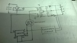
According to the datasheet the TOP259EN/YN will support 128W in a wall adapter or 238W in an open-frame design with good heat-sinking, using 230VAC input. The TOP259 would be the easiest to control(feedback) as it can be done very easily with a zener diode and an opto-coupler. The datasheet for the TOP259 has a couple working examples of lower-power designs that could easily be scaled up to your 100W requirement. Also since you are looking for a +30V, 0V, -30V DC output, this could easily be achieved by winding your transformer's secondary with a center-tap(0V) and an equal number of turns before and after the center-tap. The feedback loop would only monitor the +30V rail but since the -30V would be the mirrored half of the same winding, the negative voltage should be just as solid as the positive. I've never personally used the TOP-Switch series of controllers but I have used their "little brothers" TNY-Switch controllers and based on the datasheets they function and are controlled almost identically. They are very simple flyback power supplies, the switching transistor is built into the controller(no need for an external MOSFET), and feedback is accomplished with a zener-diode and an opto-coupler. If you wanted to be able to adjust the output so that you could fine-tune it to exactly 30VDC then you could replace the zener-based circuit with a TL431 programable shunt regulator with a tiny POT attached to adjust the triggering of the TL431. It all depends on how exact the 30VDC has to be.
For example: You could use a 28V Zener-Diode to trigger a PS2561 opto-coupler for your feedback. The diode in the OC has a MAX forward voltage drop of 1.4V(Typ is 1.2V) and a forward current of 30mA. You add the 28V from the zener with the 1.2V-1.4V drop of the diode and your output voltage would be around 29.2-29.4VDC. You would choose the size of the resistor between the zener and the OC based on the 30mA current requirement of the OC.
-Brad

